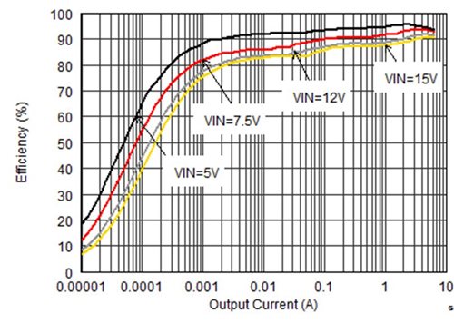
Power conversion efficiency of TI's TPS62180
When you think of high efficiency, what do you think of? I think of lower Rdson MOSFETs, larger inductors with lower DCR, and of course, lower switching frequencies. All of these things produce higher full load efficiencies, while lower DCR and lower switching frequencies also produce higher light load efficiencies. Lower Rdson MOSFETs typically have higher gate charges which produce lower light load efficiencies.
What enables smaller sizes? Well, of course, higher switching frequencies! It’s no coincidence that the TPS626xx devices operate with switching frequencies near 6 MHz to keep the total solution size under 12 mm2. And many of these discrete ICs are used in the TPS826xx MicroSIP family to shrink the total solution size down below 7 mm2!
But with higher switching frequencies comes lower efficiency. How can we combine higher efficiency and smaller size for applications demanding it, such as tablets and servers? Automatic Efficiency Enhancement (AEETM) is how!
In the TPS62180, AEE combines multiple power saving features to keep both the heavy and light load efficiencies high. At very light loads, a power save mode is used to prevent efficiency-draining forced PWM mode with its negative inductor current. Negative inductor current prolongs the losses in the switching elements since current always flows, while also stealing energy from the output and moving it back to the input with an efficiency loss.
At medium loads, the second phase activates, and the load current is shared evenly between both phases. A multi-phase converter reduces conduction losses by dividing the current equally between two or more MOSFETs. As an example of the power loss reduction, consider a 4-A load current. If this were in a single phase, the I2R losses would equal 16 * Rdson. But with a 2-phase converter, the total conduction losses through the same MOSFETs are (4 * Rdson) * 2 or half of the previous case.
Finally, AEE reduces the switching frequency when a high frequency is not needed. With a given output inductor, the switching frequency only needs to be high enough so the full output current can be delivered without reaching current limit. A higher switching frequency creates lower inductor current ripple, which enables peak current limit converters to deliver a higher average output current. Since the ripple current depends on input and output voltage and switching frequency, a high switching frequency is not always needed to get a low ripple current and not reach current limit. By reducing the switching frequency when the ripple current is already low, higher efficiency is achieved.
AEE in the TPS62180 enables smaller size through the IC’s package (2 x 3 mm WCSP) and multi-phase operation. For a multi-phase converter, the inductors need only be rated for a fraction of the total output current. Whereas a single-phase 6-A design might require an inductor that is 4 x 4 mm. A 6-A, 2-phase design may use inductors as small as a 2016 (2 x 1.6 mm) size.
What are you designing that requires small size and high efficiency?

