

Extended battery life is a common design requirement across a variety of applications. Whether it’s for toys or water meters, designers have various techniques at their disposal to improve battery life. In this post, I will illustrate one such technique that involves strategically bypassing a low dropout linear regulator (LDO).
Generating the rail
Using an LDO is a common way to generate a regulated voltage from the battery. This is especially true with a single-cell lithium-ion (Li-ion) battery that outputs 4.2V when fully charged.
Let’s say that you want to generate 3.3V for a microcontroller (MCU) with a supply voltage range of 3V to 3.6V and you chose the TPS706 to generate this rail. Figure 1 illustrates this circuit.

Figure 1: The TPS706 regulating 3.3V from the battery
Despite the simplicity of this circuit, it has some limitations. Chief among these is dropout, which will cause the LDO to cease regulation and possibly put the supply voltage of the MCU outside specification.
The implications of dropout
You can expect the voltage of the Li-ion battery to drop as the battery discharges. Figure 2 shows an example discharge curve.

Figure 2: Li-ion battery voltage falling over time
This can be troubling when you remember that the LDO risks entering dropout as the input voltage approaches the regulated output voltage. At a certain point, the battery voltage will drop so low that the TPS706 will no longer be able to regulate 3.3V. Instead, the output voltage will begin to track the battery voltage at a difference equal to the dropout voltage.
The TPS706 specifies a typical dropout voltage of 295mV when the output current is 50mA and the output voltage is 3.3V. Thus, it is possible that the LDO could enter dropout once the battery voltage drops below 3.6V. Figure 3 offers an example of such behavior.
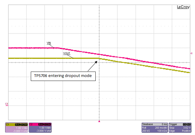
Figure 3: The TPS706 entering dropout mode
As shown, VOUT begins to droop once VIN falls to around 3.6V. Because the lower end of the MCU supply range is 3V, this is concerning – dropout can cause VOUT to fall below 3V very quickly.
Avoiding dropout
One way to circumvent this issue is to bypass the LDO before or as it enters dropout. Figure 4 illustrates how.
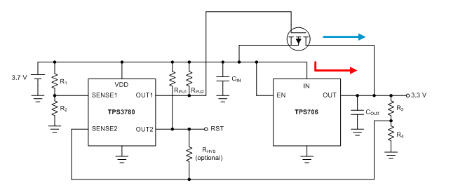
Figure 4: Using a P-channel MOSFET to bypass the LDO
In this circuit, the TPS3780, a dual-channel voltage detector, monitors the battery voltage via SENSE1. If the battery voltage should fall below 3.4V, OUT1 drives the gate of the P-channel MOSFET low. This enables the current (the blue arrow) to flow through the drain-source terminals of the MOSFET rather than through the input-output terminals of the LDO (the red arrow). Since the MOSFET has lower on-resistance than the LDO, the output voltage will more closely track the input voltage.
SENSE2 monitors the output voltage. Once the output voltage falls below 3V (or the bottom of the supply range of the MCU), OUT2 will assert low. This signal can put the MCU in reset mode.
Figure 5 shows the behavior of the circuit without the aid of the bypass MOSFET.

Figure 5: A falling input voltage without the bypass MOSFET
To simulate a battery, the input voltage is ramped down at a rate of 1V/ms. You can see that once the input voltage hits 3.4V, it takes about 100ms for the output to fall to 3V.
Now, let’s examine the behavior of the circuit that uses the bypass MOSFET, as shown in Figure 6.
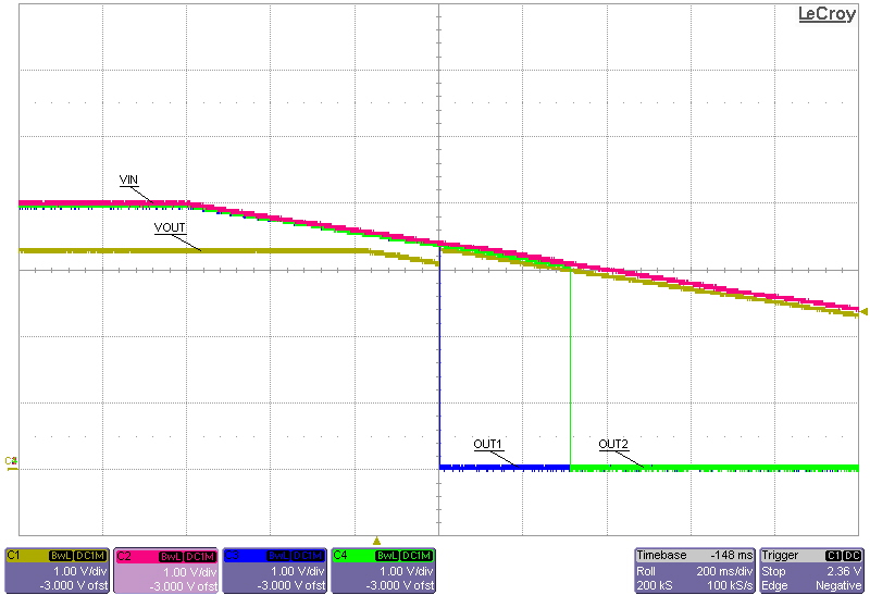
Figure 6: A falling input voltage with the bypass MOSFET
Once the input voltage falls below 3.4V, the MOSFET turns on. The output voltage is now equal to the input voltage minus the voltage drop across the MOSFET. As a result, it now takes almost 320ms for the output to reach 3V. By enhancing the PMOS device, the output voltage more closely tracks the input voltage than the LDO does in dropout. In other words, the low on-resistance of the external PMOS effectively allows for a longer battery life.
In reality, the battery voltage will fall at a slower slew rate. Therefore, using a bypass circuit can significantly extend operation time.
Current consumption
When operating off the battery, you must also consider the current consumption of the circuit. See Table 1.
|
Circuit element |
Current (μA) |
|
TPS706 |
1.3 (typ) |
|
TPS3780 |
2.09 (typ) |
|
Resistor networks |
3 (typ) |
|
Pull-up resistors |
68 (typ) when the output is low |
Table 1: Current consumption of various circuit elements
Taking this consumption into account is important, as it contributes to the overall discharge of the battery. Fortunately, however, the consumption is very low and the extra circuitry enables sustained use of the battery that outweighs the added current consumption. This is especially true for applications that require higher load currents.
Conclusion
LDOs are an effective, low current-consumptive method for generating a rail off the battery. However, dropout can cause problems with regulation when the battery voltage starts to droop. Using a MOSFET in conjunction with an LDO helps avoid this issue in order to attain the longest battery life.
Additional resources
- Read the application report for more information on resistor divider current draw and accuracy tradeoffs.
