

For a smart meter or any other system that needs to wirelessly transmit data, the challenge is the same. How do I deliver Watts of power to my radio, while using a small, robust, and extremely current-limited source such as a Lithium Thionyl chloride (Li-SOCl2) cell? For example, the radio requires 1W of energy for global systems for mobile (GSM) transmission, while the coin cell’s current should be limited to ~3mA for it to last for 10 years or more. The radio requires a much higher peak power than the coin cell delivers. A storage element is needed to buffer the required energy.
Super caps are a readily available, efficient storage medium for this energy. But how can we efficiently charge them? More importantly, which charger draws a lower power, once the super cap is charged and the system is idling? The TI Design, Energy Buffering for Long-Life Battery Applications, answers this question.
In this reference design, the TPS62740 buck converter with 360-nA quiescent current charges the super cap. Such a low IQ means that once the super cap is charged, there is extremely little current drain on the battery. And when charging the super cap, the low IQ and efficient DCS-Control power save mode topology result in efficiencies over 90%.
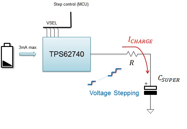
To limit the input current drawn from the coin cell, the super cap is charged through a resistor. By limiting the output current, input current is limited to less than ~3 mA as shown in the diagram below.
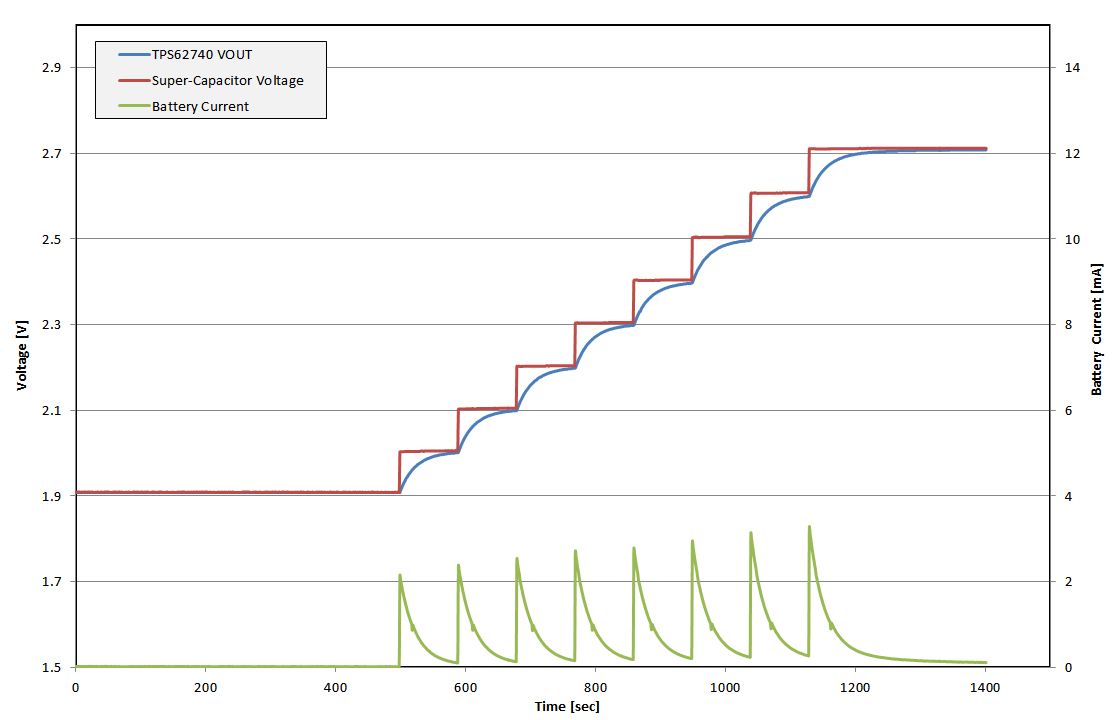
To keep this charging efficiency high, the system’s microcontroller controls the 4 VSEL input pins on the TPS62740 to adjust its output voltage. Thus, the voltage on the super cap is controllably increased in 100 mV steps, and the input current remains limited.
Let’s do a quick review: Input current -> controlled, standby current -> a very low 360 nA, energy for transmission -> stored in a super cap. An efficient design for long-life battery applications -> accomplished.
In what system would this technique extend your battery’s life?

