

 With less than a week before the Power Racing car needs to be shipped to California for Maker Faire, the TX/RX Labs team and I are working tirelessly to finish our entry for the 2015 Power Racing Series. Thankfully, the pieces of the puzzle are coming together nicely. Let’s take a look back at what we accomplished this week.
As with any project, we ran into some problems with the timing belt reduction system as we put it together. We miscalculated the spacing between the two pulleys, so the belt we ordered ended up being too short. Thankfully we were able to find the right size belt in stock at a distributor.
This week we also managed to get the new motor driver BoosterPack up and running, but once again this was not without some problems. When I initially started experimenting with the board, I kept hitting the current limit on my power supply. This seemed odd to me because each phase of the motor has a current sense and the software is designed to control the current going to the motor. Since I was hitting the current limit I knew something had to be amiss with the current sensing circuitry. After taking a look at each of the buffered current sense signals, I noticed two were idling around 1.65V while the third was near ground. Given that each of the phases was in the same state (off), I knew something had to be wrong with the third phase. I took a look at the schematic and found that the third phase was not properly biased.
The software expects zero current to equate to a mid-scale ADC reading (i.e. ½ of 3.3V or 1.65V). This allows the software to read both positive and negative currents flowing through each of the phases. With this current sense idling near ground, the software thought a large negative current was flowing through a phase and tried to counteract that by making a large positive current flow through the phase, causing the power supply to hit the current limit.

To test this theory I enabled a mode of operation in MotorWare that only uses two current sensors. Sure enough, the motor ran fine! After confirming my hypothesis I headed down to the lab to rework the board to add some additional bias circuitry.

In addition to the electronics, I made a lot of progress on the chassis and body of the vehicle. This past weekend – and against my better judgment – I scoured craigslist for the largest Power Wheels vehicle I could find. I found a used model from the late 2000’s, and after a drive out to the suburbs of Houston, I was the proud owner of a new Cadillac Escalade (Power Wheels that is…).

The Escalade was a good choice because it’s one of the largest Power Wheels vehicles in production, but I still needed to perform some minor modifications to get the body to fit over the chassis.
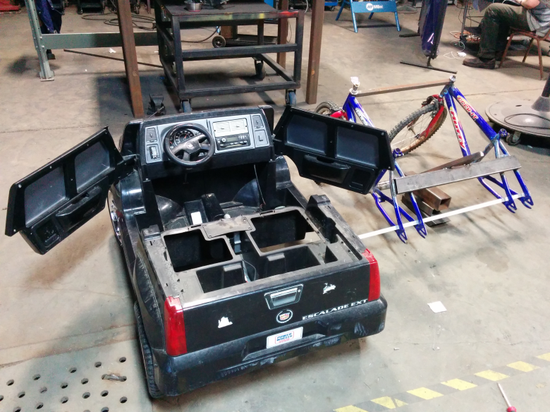
Armed with a Sawzall, some screw drivers, and a whole lot of crazy, I set about disassembling the Cadillac.

Just as important as the body is the work we got done on the chassis. TX/RX had a surplus of 2” angle iron, which I used to fabricate a battery cassette and battery mount. Now the team can have multiple battery cassettes that they can easily switch out during a race.

In addition to fabricating the battery support structure, I put together some mounting brackets for the motor and drive reduction system. The aluminum plate in the first image of this blog post will be bolted to the drilled piece of angle iron in the following image.

With less than a week left of build time, the pressure is on! Each of the pieces of the car seems to be coming together smoothly, but there are still many uncertainties that could derail the project. Come back next week for the final update of the build series and (fingers crossed) a video of the car in action!
Read the first two blogs in our Maker Faire Power Racing series:
