If you follow this blog, you most likely have heard of TI Designs – Precision, our library of high-quality reference designs for precision applications. The first thing you’ll see on the TI Designs – Precision homepage is a graphic illustrating the three levels of these designs: Reference, Verified and CerTIfied. The first two levels – Reference and Verified – are straightforward, since most engineers deal with simulations, schematics and bench measurements on a daily basis. However, the CerTIfied designator is a bit more vague.
Why is certification testing necessary, who performs the tests and what constitutes a pass or fail?
Most importantly, why is there a funny capitalized “TI” in the middle of the word? I aim to clear up those questions in today’s blog. In part two, I’ll go over the details of the most common test standards which are applicable to our precision designs.
Figure 1 – Three Levels of TI Designs – Precision
Many of our customers design products and solutions for industrial markets, and it’s well known that industrial environments – such as factory floors – can be very disruptive to analog electronics. Any circuits installed in these environments must be robust enough to withstand hefty transient voltages and currents without having a significant impact on their performance. In extreme cases, where transients are severe enough, you may end up with a small fireplace instead of a functioning circuit!
Figure 2 – Aftermath of Fatal Electrical Transients
A circuit’s ability to withstand this transient energy is called electromagnetic compatibility (EMC). The IEC (International Electrotechnical Commission), a worldwide organization which promotes international cooperation on electrical and electronic standardization, has established a set of EMC standards which have become the requirements for manufacturers wanting to do business around the world. If a product is able to pass the tests specified by these standards, it is generally accepted that it’s robust enough for even the harshest industrial environments. Herein lies the true value of CerTIfied precision designs – each of these designs has been optimized for accurate performance in almost any environment and tested against these IEC standards.
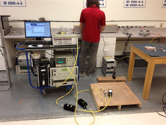
Figure 3 – EMC Testing in Progress
The type of testing done by our engineers for CerTIfied designs is called an “engineering evaluation.” This means that we, the circuit designers, travel to an accredited test center (such as NTS) and perform the suite of tests with the assistance of the test center technicians. While the test center uses standardized equipment to generate and apply the variety of transients, we are able to bring our own multimeters, oscilloscopes, or any other instruments needed to quantify the performance of our circuit under test. This is different from formal certification testing, where a third party performs the evaluation and the circuit designers are not present. Since we do not currently pursue this formal certification process, our designs are called “CerTIfied,” rather than “Certified.”
In an engineering evaluation, the circuit designer is able to define what limits make up a pass or fail condition. For example, many of our industrial analog output modules are specified to have output error less than 0.1%, relative to the output full-scale range (FSR). Therefore, it makes sense for us to use the 0.1%FSR value as our limit. Once this is established, the equipment under test will show one of four possible classes of behavior while subjected to the various tests, as shown in Table 1. Class A performance – where the circuit is essentially unaffected by transients – is the optimal case, but Class B performance can be acceptable as well.
Table 1: EMC Test Performance Classes
Stay tuned for part two, where we’ll dive into the technical specifications of the most relevant IEC tests.


