

In my previous post, we talked about three topologies for generating two high-accuracy voltage reference outputs. Today, we’ll compare the performance of these solutions from three perspectives: total error, drift tracking and matching between outputs.
Total error
Equation (1) converts specifications given as a percentage (%) to parts per million (ppm).
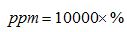
(Equation 1)
The Total Error performance metric of each voltage output depends on its initial accuracy and drift over the operating temperature range, as given in Equation (2).
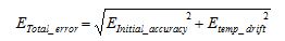
(Equation 2)
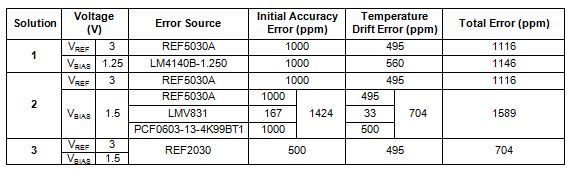
In Solution 1, as no typical drift for the LM4140B is given in the datasheet, we use the maximum drift specification, over a 70ºC temperature range for calculation. In Solution 2, the bias voltage (VBIAS) is generated from REF5030A, resistor network and a buffer. Therefore, the initial accuracy and drift can be expressed as the RSS of these three error sources, as given in Equation (1) in Part 1. Since the REF2030 and REF5030A use the box method to determine drift, the temperature range for calculations is the entire operating range, or 165ºC.
Table 1 shows that while the performance of VREF in Solution 1 is the same as Solution 2, its VBIAS output has considerably more error. Note that the error for VBIAS in Solution 2 includes the error from VREF. With high initial accuracy and low temperature drift on both outputs, Solution 3 has the lowest error of the three solutions.
Table 1: Comparison of error contributions for each output voltage
Drift tracking and matching
Another important specification for this dual output system is drift tracking, which describes the accuracy matching between two voltages over a particular temperature range, as given by Equation (3). Figure 1 shows the typical drift tracking performance of the REF2030.

(Equation 3)
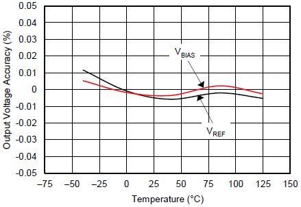
Figure 1: VREF and VBIAS tracking vs. temperature
Since we applied two independent voltage references in Solution 1, theoretically the two references may not directly track each other, so the tracking is the RSS value of their maximum temperature drifts (11 ppm/ºC). As the LM4140B is only specified from 0°C to 70ºC, this drift tracking only applies for this temperature range.
In Solution 2, since error in VREF is common to both outputs, the drift tracking (δTracking) between VREF and VBIAS only depends on drift from resistor network (δRES) and buffer (δBUF), as given by Equation (4).
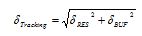
(Equation 4)
Given the initial accuracy error, we can also calculate the matching (at 25ºC) of the outputs in terms of RSS, as shown in Equation (5).
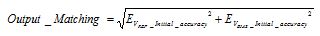
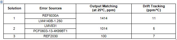
Table 2 shows a comparison summary. Note that the drift tracking and output matching in Solution 2 heavily depend on the precision of the resistors. While the tracking of the two outputs in Solution 2 is slightly better, the matching of the outputs is much worse than that in Solution 3. Actually, Solution 3 is about 900 ppm better. This means, with only a 2 ppm/°C difference in drift, it will take a 450°C of temperature shift before Solution 2 becomes the more accurate solution. For details on calculation, please refer to data.xlsx.
Table 2: Comparison of output matching and drift tracking
From our calculations we know Solution 3 has the best overall performance in most cases. However, in reality, analog engineers have to consider more than performance. Stay tuned for next week, when we compares the three solutions with respect to PCB space and cost.
Related resources:
- TIPD156: Low-Drift Bidirectional Single-Supply Low-Side Current Sensing Reference Design
- Voltage Reference Selection Basics
- Part 1: A voltage reference duel of duals

