There are two types of voltage references, shunt references and series references. Each type has its own usage conditions and the process of selecting between the two can be intimidating. Comparison tables do exist, but they typically provide little insight on how to choose one reference topology over the other for specific applications. This blog series will discuss the applications of both shunt and series references and when to use them, as well as highlight some lesser known use cases for each reference topology.
Part 1 - Shunt versus series: Which topology is right for you?
The real world is analog (for now at least), and the most common way to interface with the real world is to use analog-to-digital converters (ADCs), sensors or other application-specific integrated circuits (ICs). A voltage-reference IC provides a stable output voltage that can be used as a constant value as system voltage and temperature change. There are two types of voltage references – shunt and series – and each has its own set of strengths and use cases, listed in Table 1.
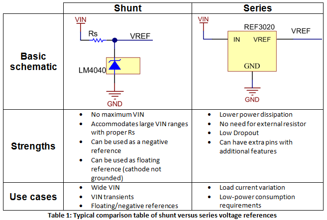
A shunt reference is functionally similar to a Zener diode, where the voltage drop across the device is constant after the device reaches a minimum operating current. The shunt reference regulates the load by acting as a constant voltage drop and shunting excess current not required by the load through the device to ground. There is no maximum input voltage rating for a shunt reference, but an external resistor , is required. The input supply will always see the maximum load current as determined by the input voltage level and the external resistor. The shunt reference will sink more or less current as the current requirements of the load change.
The external resistor must be between and , as calculated by Equations 1 and 2:
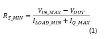
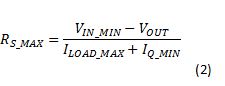
You can also use a shunt reference to create floating references and negative references, and the equations for calculating remain the same.
A series reference device does not require an external resistor, and only consumes as much current as required by the load plus a small quiescent current. However, the input voltage is passed directly into the reference device; therefore a series reference does have a maximum-rated input voltage. The series reference may include an enable pin to externally enable or disable the device to save power.
When selecting a voltage reference for your next application, be sure to keep the typical use cases below in mind.
Shunt reference use cases:
- Wide-input voltage range or high-input voltage transients.
- Negative or floating voltage references.
Series reference use cases:
- Variation in load current, where a series will see lower for lighter loads.
- Reference with sleep or shutdown operations.
In part two of “Understanding Voltage References,” I will discuss ultra-low dropout and how it is not just for the series reference.
In the meantime, visit www.ti.com/vref for more information on TI’s voltage reference products and for a detailed explanation of voltage-reference selection with respect to ADC resolution, download the white paper “Voltage Reference Selection Basics.”