

Here’s a frustrating situation: You finally get your analog-to-digital converter (ADC) up and running, but things are just a little bit off. You put in a voltage, but your ADC reports something different.
What’s wrong?
It looks like everything’s set up right. It might be a communication problem, or it could be that your ADC isn’t measuring your analog inputs correctly.
The best tools for debugging a measurement problem are a low-noise voltage source and a precision multimeter, like those shown in Figure 1. Using the voltage source as the input signal for the ADC and the precision multimeter to measure both the input and the reference of the ADC, you can compare the expected result to what the ADC reports. Just make sure that the input voltage is referenced to a DC voltage within the input range.
 Figure 1: A low-noise voltage source and precision multimeter are two great analog debugging tools
Remember that the ADC measures the input and outputs a conversion code proportional to the ratio of the input to the reference. If you have a 24-bit ADC with a bipolar range of ±VREF, the output data is defined by Equation 1:

You can make several analog input measurements in the full scale and compare the expected output code to what your ADC reports. Using this data, you can calculate how far off your results are. You can also determine if the error is a gain error or an offset error. Just make sure that you get an accurate multimeter reading by measuring the signal directly at the input pins of the device.
If the difference is small, the ADC might just need calibrating. Precision ADCs often require a calibration command to remove offset and gain errors.
Perhaps you try increasing the input voltage, but the ADC code doesn’t move. It’s possible that you’re running out of input range because the input buffer limits the signal. As an example, the input buffer in the 24-bit, 30-kSPS ADS1255 extends to GND on the bottom end and AVDD -2V on the upper end.
For other devices (like the 24-bit, 2-kSPS ADS1220), the buffer is a full analog programmable gain amplifier (PGA). In those cases, you need to consider the PGA gain and the input and output common-mode range or the PGA may limit your measurement.
Figure 2 shows the PGA diagram from the ADS1220 data sheet’s PGA Common-Mode Voltage Requirements section describing these limitations.
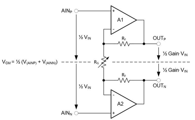
Figure 2: PGA common-mode voltage as described in the ADS1220 datasheet
Another potential source of error could be located in the input filtering. Large-input series resistance can react with input bias currents to add voltage error to the measurement. Also, using input filtering with too low of a cutoff frequency can interfere with the sampling nature of the ADC. For each modulator clock, the input and reference are sampled with an input capacitor. This sampling must settle within the modulator clock period. Since the inputs are periodically sampled and discharged, inductances in the input path can cause voltage errors because of the periodic sampling.
Like the analog inputs, you’ll need to treat reference inputs similarly. Large-input impedances will cause similar errors.
It is also important to verify that the reference is operating properly. For example, the 24-bit, 2-kSPS ADS1248’s internal reference requires between 1μF and 47μF of load capacitance. Additionally, the VREFCOM pin must have a path of less than 10Ω to an AC ground node. Without meeting these two conditions, the reference may become unstable. External references can have similar problems with stability. These unusual errors may not be detectable with a multimeter and may require an oscilloscope to track down.
In highly integrated devices, like the ADS1248, many functions are used in specific situations. If these options are used improperly, they can interfere with the measurement.
Figure 3 shows a block diagram of the ADS1248. The red circles are blocks that may interfere with the measured value if left on when not use.

Figure 3: A block diagram of the ADS1248 showing blocks that can impart errors if used improperly
Improper grounding of the analog and digital sections can lead to ground-loop voltages in the circuit. This can interfere with the input signal as well as the reference voltage. Good layout can reduce these errors in the measurement. Other circuitry around the ADC, like leaky electrostatic discharge (ESD) diodes or external buffers, can also introduce errors.
When the measurements of your ADC aren’t quite right, good debugging can help you determine what’s wrong. The next time your ADC isn’t giving you the right result, try checking the common sources of error I’ve covered in this post.
Good luck debugging!
Additional resources:
- Learn more about our ADCs in our Data Converter Learning Center.
- Take a look at how to improve your ADC system power supply rejection by fellow TI applications engineer Ryan Andrews.
- Learn all about PGA input range requirements by fellow TI applications engineer Bryan Lizon.
- Don’t forget to check out other posts by my colleagues with design tips and delta-sigma ADC basics.
