

Many newcomers to analog-to-digital converters (ADCs) wonder how to convert their ADC code to a voltage. Or perhaps their question is specific to the application, such as how to convert the ADC code back to a physical quantity like current, temperature, weight or pressure. In this two-part blog series, I’ll address how to perform this math conversion for various applications. In part 1, I’ll explain how to covert an ADC code back to its corresponding voltage. In part 2, I’ll use a few application examples to show how to calculate the physical parameter of interest from the measured voltage.
Converting codes to voltages
ADCs sample analog signals provide a quantized digital code to represent the input signal. The digital output codes get post-processed and results may be reported to an operator who will use this information to make decisions and take actions. Therefore, it is important to correctly relate the digital codes back to the analog signals they represent.
In general, the ADC input voltage is related to the output code by a simple relationship, as shown in Equation 1:

where VIN (V) is the ADC’s input voltage (referred to the input, as described below), Output Code is the ADC’s digital-output code in decimal format (the number of counts) and LSB Size is the value or weight of the least significant bit (LSB) in the ADC code.
Equation 1 is a general equation that can work for any ADC. It doesn’t matter if the ADC’s output code is in straight binary or two’s complement format, as long as the binary number is correctly converted to its equivalent decimal value.
Determining LSB size
Once an ADC conversion completes, calculate the input voltage by multiplying the decimal value of the output code by the LSB size. Knowing the LSB size is the key to converting between codes and voltages.
Equation 2 determines LSB size:
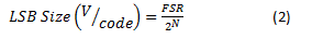
where FSR is the full-scale input range of the ADC (in volts) proportional to the reference voltage and N is the number of bits in the ADC output code. 2N equals the total number of ADC codes.
The LSB size is equal to the full-scale input range (FSR) divided by the total number of ADC codes. This is equivalent to the step size of each code required to cover the entire input range. Figure 1 shows the step function of a 4-bit ADC (24 = 16 codes), which maps input voltages to output codes.

Figure 1: ADC input transfer function (N = 4)
Full-scale range and input-referred voltage
It is important to pay attention to the FSR of the particular ADC you’re using, as this varies between ADCs. FSR is always proportional to the reference voltage and may also depend on any internal gain, as Equation 3 shows:
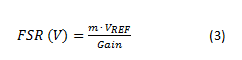
where VREF is the ADC’s reference voltage (in volts); m is the reference voltage scaling factor (for example, if the ADC’s differential input range allows for input voltages from -VREF to VREF, then m = 2 so that FSR = 2VREF) and Gain is the ADC’s internal gain (if any; otherwise equal to 1 V/V). I included gain in this equation in order to calculate the input-referred voltage in cases where the ADC incorporates a gain stage, as shown in Figure 2.
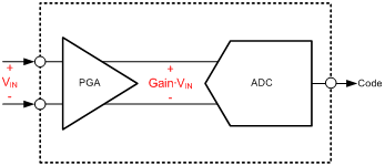
Figure 2: Input-referred voltage
It is common for delta-sigma ADCs to integrate a programmable gain amplifier (PGA) gain stage prior to the ADC inputs; that’s why Equation 3 includes the Gain term. By including PGA gain in the FSR calculation, the LSB size calculation accounts for this gain. This means that when you multiply the output code by the LSB size, the result is the input-referred voltage (VIN) prior to the PGA input, as seen in Figure 2, and not the amplified (output-referred) voltage. Note that if the system uses additional signal conditioning prior to the ADC, the effects of this circuitry may require extra calculations to determine the system’s input-referred voltage (prior to the signal-conditioning circuitry).
Example code
In most cases, the ADC code is read by a microcontroller in 8-bit segments and concatenated into a 32-bit data type. If the ADC’s resolution is less than 32 bits and the output code is signed, the data will need to be sign-extended into the 32-bit integer data type to preserve the sign. The code in Figure 3 shows an example of this operation.
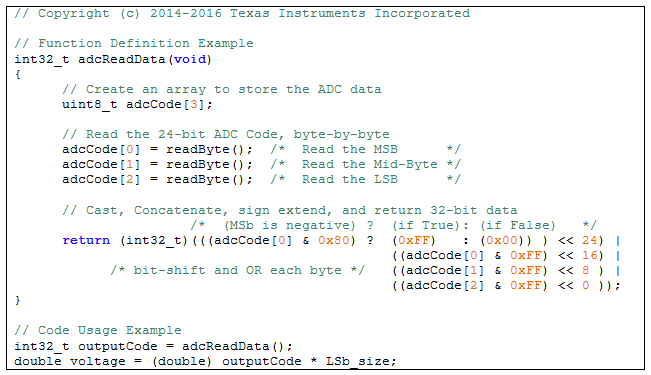
Figure 3: Example code of reading 24-bit ADC data
Now that you know how to convert ADC codes to their corresponding input voltages, the next step is to understand the relationship between the ADC input voltage and the physical parameter of interest. I will look at this more in part 2. In the meantime, please login and leave a comment below or check out the Data Converter Learning Center for more ADC resources.
Additional resources
- Read more delta-sigma ADC blog posts.
- Find commonly used analog design formulas in the “Analog Engineer’s Pocket Reference Guide” e-book.
- Get started on your design with a TI Design - Precision reference designs.
- Explore TI’s portfolio of precision ADCs and find related technical resources for your design.

