

This post is co-authored by Rahul Prakash.
Pop quiz: What’s the most requested feature in modern-day industrial systems?
If you guessed accuracy, then you are correct. In the past, only the test and measurement market needed highly accurate signal-chain components, but now other industrial markets such as factory automation, optical networking and medical require high accuracy as well. A precision digital to analog converter (DAC) fine-tunes gain and offset, and corrects other nonlinearity in the signal chain. Therefore, the burden of making a signal precise largely falls on the precision DAC calibrating it.
Nothing is perfect in analog integrated circuits, and precision DACs are no different. The main source of DC errors in a precision DAC are offset error (OE), gain (GE) and integral nonlinearity (INL). You can calibrate OE and GE with a simple two-point calibration scheme. INL errors need a more extensive calibration scheme as well as external memory to store the algorithm, which places a significant burden on the designer. Therefore, minimizing the INL of the DAC is key to enhancing accuracy.
The most common precision DAC architectures are R2R ladder- or resistor string-based topologies. The resistor-string DAC as shown in Figure 1 is a series of equally sized resistors with a tap point between each resistor. Depending on the input digital code, the appropriate tap point will be switched to the output buffer. An N-bit resistor-string DAC would need 2^N resistors.
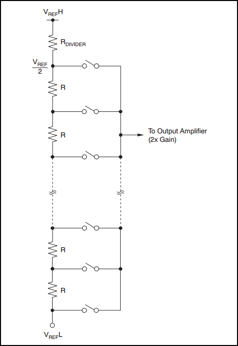
Figure 1: Resistor string architecture
On the other hand, the R2R ladder DAC is a smarter version of string DAC with fewer resistors needed for same resolution. Figure 2 shows that the R2R ladder DAC architecture needs 3N+1 total R-unit value resistors. To learn more about Precision DAC architecture, watch the “Precision DAC architecture overview” video.
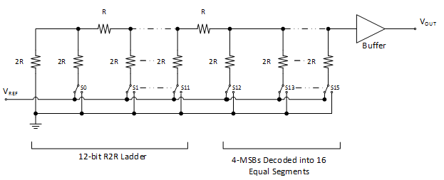
Figure 2: R2R ladder architecture
The biggest contributor to INL for these DAC architectures is a mismatch in resistors. Therefore, designers must employ additional design, layout and trimming techniques to counter the effect of these mismatches. The process of changing the resistor value for matching is called trimming, which I will go over now.
Trimming a resistor string DAC is prohibitive due to the large number of resistors. There are far fewer resistors to trim in the R2R ladder DAC architecture compared to other DAC architectures.
The trim procedure begins with the first lower lower significant bit (LSB) requiring trim. For a 16-bit DAC with data bits S0 (LSB) to S15 most significant bit (MSB), assume that the first trimmed bit is S5. The trim routine begins by looking at the error between adjacent codes 32 to 33. Ideally, the voltage-change difference between adjacent codes would be 1LSB. Assuming that the trim is bidirectional, the error for S5 is adjustable up or down depending on the initial error.
Upon completing the trim for S5, mathematically add the delta amount trimmed of all major carry errors for bits above S5 (S6, S7, etc.). Continue this procedure until you reach the MSB major carry bit code. At the end of this trim, the resulting DAC not only exhibits 16-bit monotonicity but also achieves sub-1LSB INL, as shown in Figure 3 – the INL of the DAC80004.
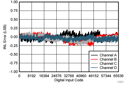
Figure 3: DAC80004 linearity error vs. digital input code
R2R ladder-based DACs are suited to applications that demand accuracy because the R2R ladder design allows practical trimming to achieve ultra-high accuracy – <1LSB INL.
If you have any unique high-precision applications or if there is anything you’d like to learn more about, please log in and share it with us in the comments section below.
Additional resources
- Check out these blog posts by Kevin Duke:
- To learn more about OE, GE and INL parameters: “DAC Essentials: How accurate is your DAC?”
- To understand the resistor string architecture: “DAC Essentials: String theory.”
- To understand the R2R ladder architecture: “DAC Essentials: The resistor ladder.”
- Download applications of precision DACs from our TI Designs precision reference design library.
- Take a look at the resources in the Precision DAC Learning Center, which includes information for beginners, intermediate level and advanced designers.
- Learn about TI’s data converter portfolio and find technical resources.
- Watch the Lessons for Precision DACs training series for more information on precision DAC architectures:
