

In portable electronics designs, typical battery-monitoring systems measure battery voltage and battery current to detect when the battery needs charging or replacement. In this post, I’ll demonstrate battery-voltage and current-monitoring circuitry for cost-optimized systems using operational amplifiers (op amps).
Op amps used in battery-monitoring circuitry must meet the required accuracy levels while consuming minimal power-supply quiescent current, iQ, to conserve battery life. Table 1 lists the key specifications for two new op amps, the TLVx369 and TLVx379 families, which are designed for low-power, cost-sensitive applications.
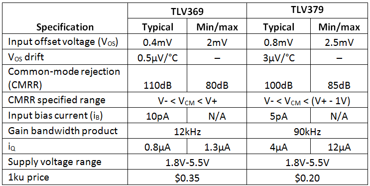
Table 1: Key specifications for TLV369 and TLV379 op amps
In figure 1, you will see an example battery-voltage measurement circuit using the TLV379 configured as a unity-gain buffer. To prevent violations of the amplifier’s common-mode input voltage range or output voltage swing, the battery is divided down using R1 and R2. In this case, a 1.8V-5.5V battery voltage will create a 0.393V-1.2V output voltage, which fits within the common 0V-1.2V range for analog-to-digital converters (ADCs) on many low-power microcontrollers.
Equation 1 shows the transfer function for the circuit in Figure 1. Be sure to use high-value resistors for the divider to minimize current consumption. You can place a low-pass filter at the output of the circuit to limit the signal bandwidth and output noise. However, like most low-power op amps, the TLV379 does not perform well while driving capacitive loads, so check the stability of the circuit when designing output filters with capacitances to GND.
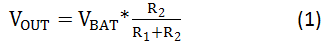
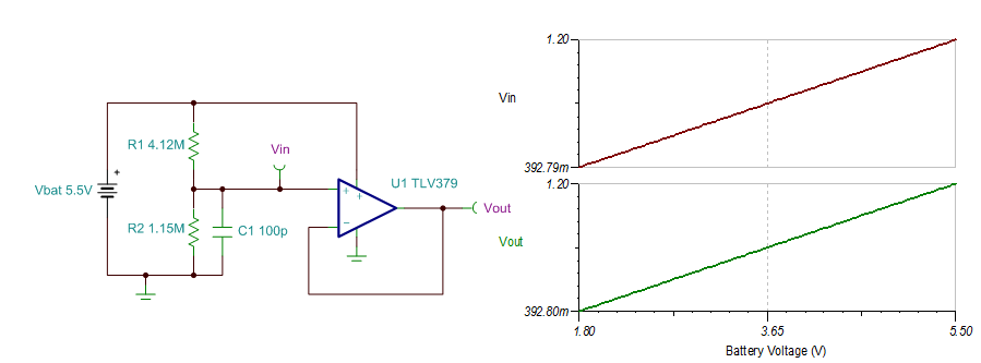
Figure 1: Battery-voltage measurement circuit using the TLV379
The main error contributors in the circuit shown in Figure 1 are the tolerance of the resistors in the divider and the offset voltage of the op amp. Other error sources come from the op-amp’s CMRR and the input bias current flowing through the voltage-divider resistors.
Table 2 uses the typical specifications for the TLV379 listed in Table 1 to calculate expected circuit performance. The resistor divider tolerance, RTOL, is set to 0.1%.
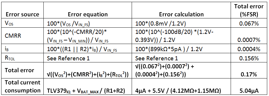
Table 2: Error calculations for the TLV379 voltage-measurement circuit shown in Figure 1
Measuring the voltage drop across a low-side current-shunt resistor is often the simplest method to determine battery/load current. Figure 2 shows an example low-side current-sensing circuit using the TLV379. The circuit in Figure 2 was designed to create a 0V-1.2V output voltage for a 0A-1A load current, iLOAD. Equations 2 and 3 calculate the input voltage, VIN, and output voltage, VOUT, respectively; you can use these equations to adjust the circuit for other ranges.
In Figure 2, the shunt voltage, VSHUNT, was limited to 100mV with the maximum 1A load current; you could use other VSHUNT values depending on what the load can tolerate. Be sure to make a good Kelvin (or four-wire) connection across the shunt resistor, RS, to reduce the effects of printed circuit board (PCB) impedances.
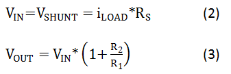
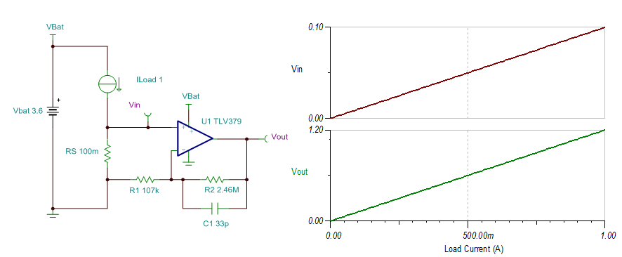
Figure 2: Low-side battery current-measurement circuit using the TLV379
Table 3 lists the error calculations for the circuit in Figure 2. Shunt-resistor values with <1Ω tolerances are typically 1%, which matches well with the error from the TLV379 VOS. The tolerance of the gain-setting resistors, R1 and R2 is set to 0.1%.
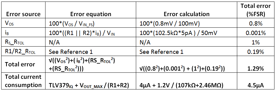
Table 3: Error calculations for the TLV379 current-measurement circuit shown in Figure 2
The voltage drop across the shunt resistor in a low-side current-measurement circuit affects the voltage potential of the load GND, which is undesirable in some applications. Figure 3 shows a high-side battery-current-sensing circuit using the TLV369, which features a rail-to-rail input stage with >100dB of CMRR over the full supply voltage range. The circuit was designed to keep the output voltage below 1.2V for a 1A load current and 5.5V battery voltage.
Equations 4, 5 and 6 show simplified transfer functions for the circuit. The bias voltage, VBIAS, created from the resistor divider pushes the output voltage away from the negative rail, allowing for current measurements down to 0A. You must combine this circuit with the battery-voltage measurement to obtain the value of VBIAS. While I didn’t include them in this post, the error calculations for the circuit in Figure 3 are similar to those shown in Table 3.
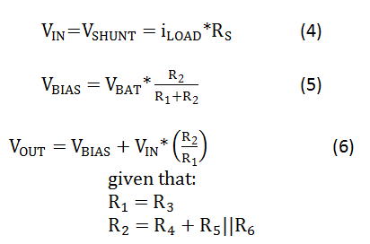
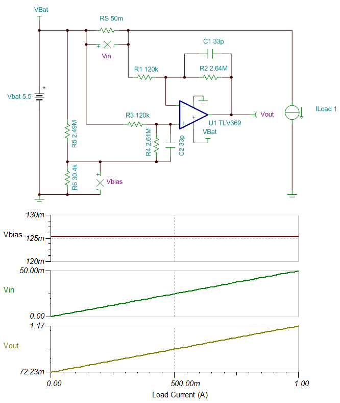
Figure 3: High-side battery-current measurement circuit using the TLV369
Battery-powered electronics almost always include battery-voltage and current-monitoring circuitry for gauging and protection purposes. In this post, I provided circuit examples for a voltage-measurement circuit and both low- and high-side current-sensing circuits using some of our newest op amps, which provide an excellent price-to-performance ratio for cost-sensitive systems.
Have questions about other op-amp designs? Log in and leave a comment.
Additional resources
- Read my colleague, Pete Semig’s blog, “Resistor Divider Drift: 5ppm + 5ppm = 5ppm” which I used to determine the gain error from the resistor divider in circuit 1.
- See TI’s portfolio of performance op amps for cost-conscious applications.
- Watch more than 40 on-demand precision amplifier training videos in our TI Precision Labs – Op Amps series.
- Find commonly used analog design formulas in the Analog Engineer’s Pocket Reference e-book.

