

Welcome to the final installment of this blog series discussing electromagnetic compatibility (EMC) testing. In Parts 1, 2 and 3 we discussed the background of certification testing, as well as the specifications for electrostatic discharge (ESD), radiated electromagnetic interference (EMI) immunity, electrical fast transients (EFT) and surge tests. In this installment, I’ll describe the tests for conducted EMI and radiated EMI emissions. Finally, I will provide some general tips on how to pass the most common EMC tests.
IEC 61000-4-6: conducted EMI immunity
Electronic products are often installed in locations near radio frequency (RF) transmitters. These transmitters create electromagnetic fields that can have a significant impact on the functionality of other electronics. The International Electrotechnical Commission (IEC) 61000-4-6 test standard, given in Table 1, relates to the conducted immunity requirements of electrical and electronic equipment to disturbances coming from RF transmitters in the frequency range of 15kHz to 80MHz. The principle of the test is to excite an electromagnetic disturbance field within the device under test by applying RF stress to certain cables entering it. A circular injection probe applies the test field to the device’s cables, and another probe monitors the intensity of the field. Figure 1 shows the complete test setup.
Table 1: IEC 61000-4-6 test levels
| Product Type | Electric field (V/m) | Frequency range (MHz) | Amplitude modulation depth (%) | Amplitude modulation frequency (kHz) |
| Residential, commercial, light industrial | 3 | 0.15-80 | 80 | 1 |
| Industrial | 10 | 0.15-80 | 80 | 1 |
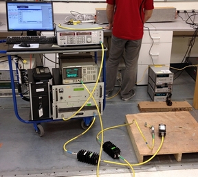
Figure 1: IEC 61000-4-6 conducted EMI immunity test hardware setup
FCC Title 47, Section 15.109: radiated emission limit
The Federal Communications Commission (FCC) has specified a limit to the amount of EMI that can radiate from electronic devices, as shown in Table 2. This standard helps maintain lower levels of radiated interference in order to reduce problems caused by radiative coupling.
The radiated emissions test is performed in the same type of anechoic chamber as the radiated EMI immunity test described in Part 2. In this case, the device under test acts as the EMI transmitter and the test chamber’s antenna acts as a receiver. The antenna measures the intensity of the electric field at a specified distance away from the device under test.
Table 2: FCC radiated emissions limits
|
|
Class B devices at 3m (dBµV/m) | ||
| 30-88MHz | 39.1 | 40.0 | ||
| 88-216MHz | 43.5 | 43.5 | ||
| 216-960MHz | 46.4 | 46.0 | ||
| > 960MHz | 49.5 | 54.0 |
The test results plot the measured radiated emissions against the limits set by the FCC. Figure 2 shows an example test result for a Class B device at 3m.
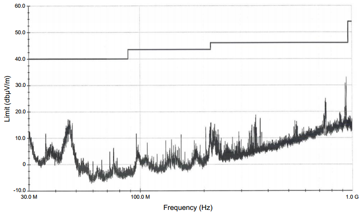
Figure 2: Example radiated EMI emissions test results
Transient protection tips
- Place a 100nF bypass capacitor across the power-supply lines close to the circuit board’s power connectors. This capacitance helps attenuate transient energy before it flows to other protection circuitry.
- Connect bidirectional transient voltage suppressor (TVS) diodes between the recommended bypass capacitors and the power-supply pins of your device. These diodes divert harmful transient energy to ground. Ensure that the working voltage and breakdown voltage of the TVS match the requirements of your system.
- Place ferrite beads in series with the power-supply lines to provide a large series impedance for high-frequency transients.
- Use a copper ground plane on both layers of the printed circuit board (PCB) to provide a low-impedance path for transient energy.
- Install large-ferrite-core wire terminators on the wires providing power to the board, making sure to wrap the wires around the cores several times for best EMI rejection.
The simplified circuit shown in Figure 3 (from the TIPD155) is an excellent example of a robust protection scheme that will pass the standard set of EMC tests.

Figure 3: Simplified schematic showing protection components
Related resources:
- Bridge Sensor Signal Conditioner with Current Loop Output, EMC Protection reference design.
- Part 1 – Get CerTIfied, not certi-FRIED! Electromagnetic compatibility testing explained.
- Part 2 – Get CerTIfied, not certi-FRIED! Electromagnetic compatibility testing explained.
- Part 3 – Get CerTIfied, not certi-FRIED! Electromagnetic compatibility testing explained.
- Learn about TI’s portfolio of precision DACs and find related technical resources for your design.
