

Welcome to part two of this blog series discussing electromagnetic compatibility (EMC) testing. In part one, we discussed the need for certification testing, who performs the tests, and what constitutes a pass or fail condition. This time, we’re going to dive right into the technical specifications of some of the most common tests.
IEC 61000-4-2: ESD (Electrostatic discharge)
ESD (Electrostatic discharge) is one of the most common forms of transients in electronic systems. ESD results from conditions which allow the build up of electrical charge from contact and separation of two non-conductive materials. When the charged body is brought in proximity of another object of lower potential, energy is released in the form of ESD.
IEC 61000-4-2 defines four threat levels which depend on material type, ambient humidity, and expected amount of handling. Level 1 is the least severe while level 4 is the most severe. IEC 61000-4-2 also specifies the parameters of the current waveform associated with the ESD.
Table 1: IEC 61000-4-2 Severity Levels and Test Voltages
|
Threat Level |
Relative Humidity As Low As (%) |
Material Type |
Maximum Charge Voltage (kV) |
Test Voltage – Contact Discharge (kV) |
Test Voltage – Air Discharge (kV) |
|
1 |
35 |
Antistatic |
2 |
2 |
2 |
|
2 |
10 |
Antistatic |
4 |
4 |
4 |
|
3 |
50 |
Synthetic |
8 |
6 |
8 |
|
4 |
10 |
Synthetic |
15 |
8 |
15 |

Figure 1: IEC 61000-4-2 ESD Current Waveform
Table 2: IEC 61000-4-2 Waveform Parameters
|
Threat Level |
Indicated Voltage (kV) |
First Peak Current of Discharge ±10% (A) |
Rise Time with Discharge Switch (ns) |
Current (±30%) at 30 ns (A) |
Current (±30%) at 60 ns (A) |
|
1 |
2 |
7.5 |
0.7 to 1 |
4 |
2 |
|
2 |
4 |
15 |
0.7 to 1 |
8 |
4 |
|
3 |
6 |
22.5 |
0.7 to 1 |
12 |
6 |
|
4 |
8 |
30 |
0.7 to 1 |
16 |
8 |
Figure 2 illustrates the test hardware setup for the different ESD tests. Typically four tests are performed:
1. Indirect discharge to VCP (Vertical Coupling Plane): The device under test is placed 10 cm away from a vertically-oriented metal plane. ESD is discharged ten times to the side of the plane.
2. Indirect discharge to HCP (Horizontal Coupling Plane): The device under test is placed on an insulating mat, which is on a table with a horizontal metal plane. ESD is discharged ten times on the side of the plane.
3. Air discharge: ESD is discharged ten times approximately 1 cm from the device under test.
4. Contact discharge: The tip of the ESD generator is placed in contact with the device under test. ESD is discharged ten times.
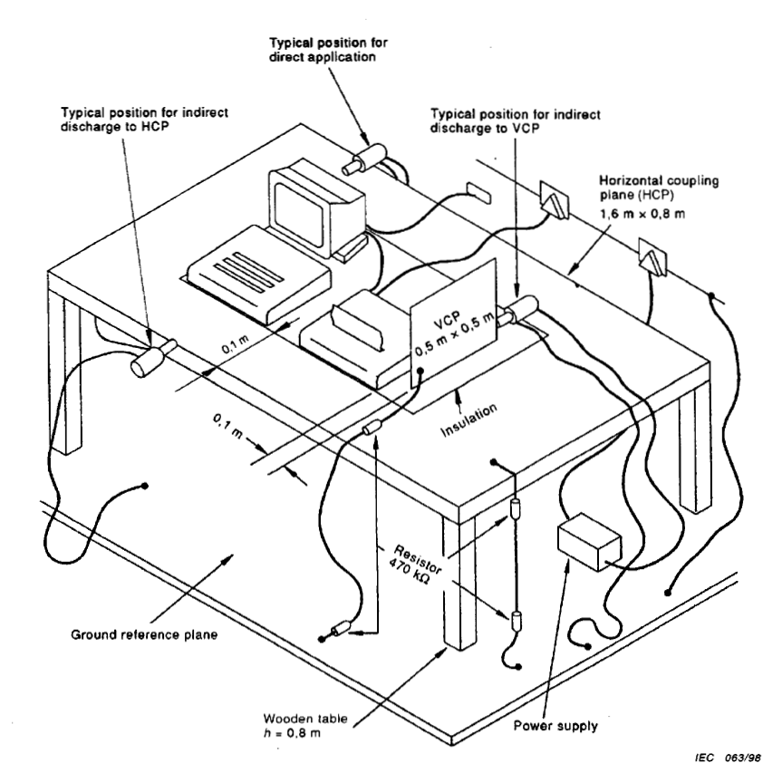
Figure 2: IEC 61000-4-2 ESD Test Hardware Setup
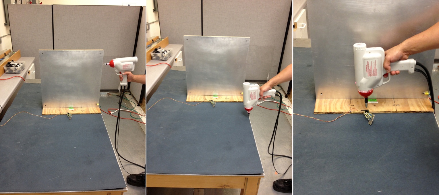
Figure 3: IEC 61000-4-2 ESD Tests – VCP, HCP, Air Discharge
IEC 61000-4-3: Radiated EMI (Electromagnetic Interference) Immunity
Electronic products are often installed in locations near RF (radio frequency) transmitters. These transmitters create electromagnetic fields which can have a significant impact on the functionality of other electronics. The IEC 61000-4-3 standard relates to the radiated immunity requirements of electrical and electronic equipment to disturbances coming from RF transmitters in the frequency range of 80 MHz to 1 GHz.
Table 3: IEC 61000-4-3 Test Levels
|
Level |
Test Field Strength (V/m) |
|
1 |
1 |
|
2 |
3 |
|
3 |
10 |
|
4 |
30 |
|
x |
Special |
|
Note: x is an open test level and the associated field strength may be any value. |
|
The test is performed inside a shielded, anechoic chamber which must be large enough to maintain a uniform field with respect to the device under test. RF absorbers are used to damp reflections in the chamber. An RF signal generator, often controlled by software, creates the test signals which are amplified by a power amplifier and transmitted by a field generating antenna. The antenna can be set to vertical and horizontal orientations.
The device under test is placed on a nonconductive table a fixed distance away from the antenna. The table sits on a motorized turntable which allows the device under test to be rotated. A field sensor is placed adjacent to the device under test in order to calibrate and monitor the intensity of the electromagnetic field.
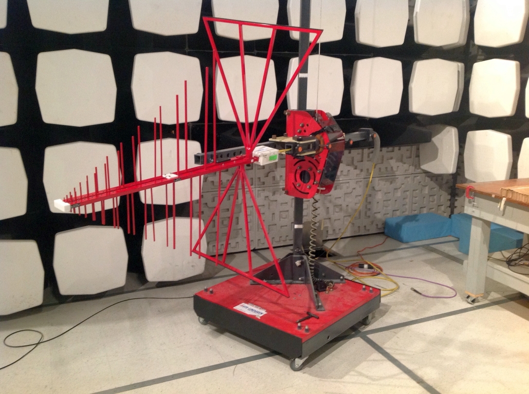
Figure 4: Log-Periodic Dipole Antenna – Vertical Orientation
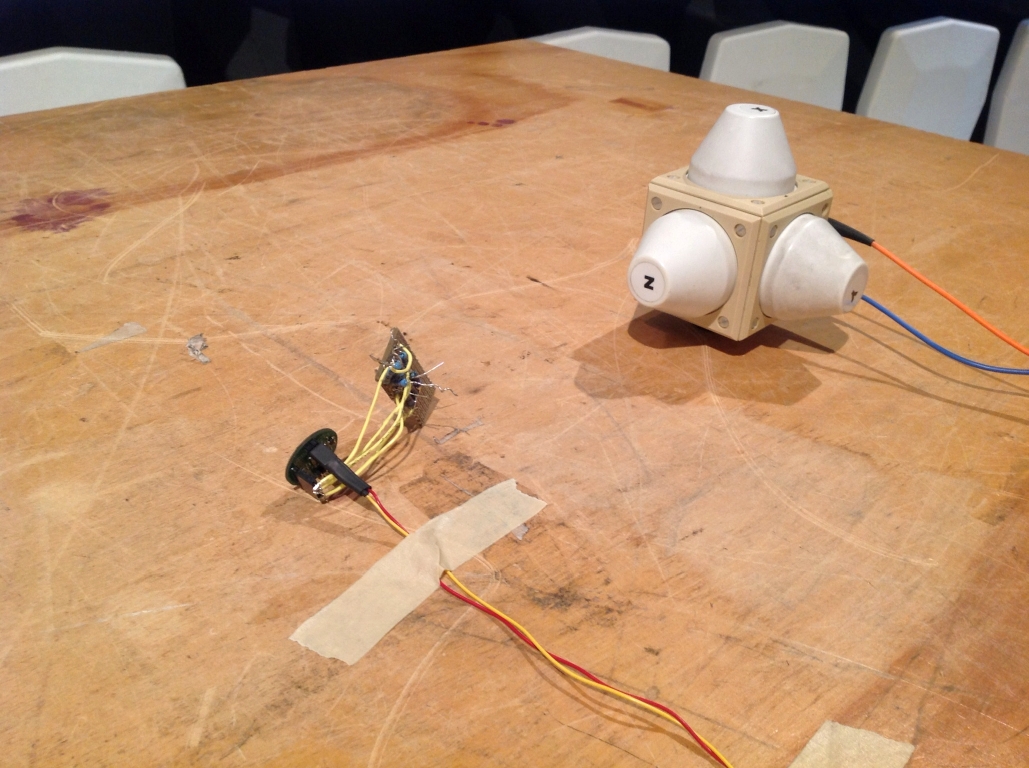
Figure 5: Device under Test (with Sensor Test Board) and Field Sensor
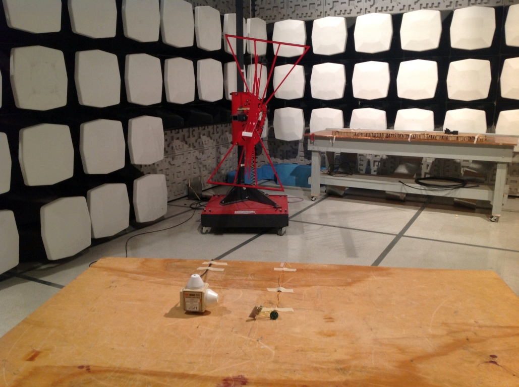
Figure 6: IEC 61000-4-3 Full Test Chamber Setup
Stay tuned for the next installment in the series, where we’ll cover the specifications of more tests such as electrical fast transients (EFT) and surge.
