

I recently performed some tests in the lab and noticed a strange ringing on the output signal. After troubleshooting the problem, I managed to trace the ringing back to the input signal. Figure 1 shows the input signal of my circuit with the ringing boxed in red. I needed to find the cause of the ringing since a clean step response was expected. It turns out that my lab equipment was not properly terminated. This blog post describes how to properly terminate your lab equipment and the importance of this technique.

Figure 1: Unknown ringing
Figure 2 shows the test circuit with source impedance, ZS, equal to the default 50Ω source impedance of the lab equipment and input impedance Zi.- These can vary depending on what is needed for the circuit.
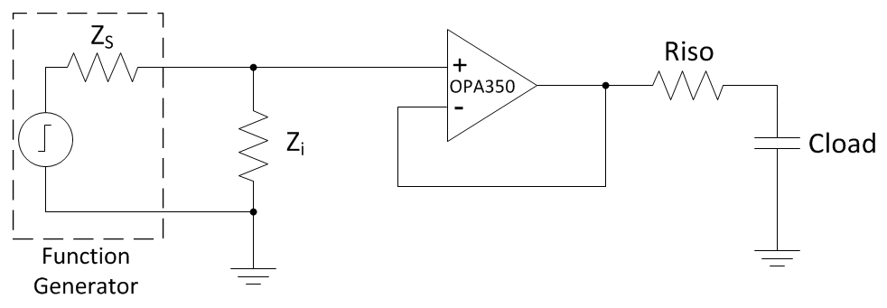
Figure 2: Test Circuit
Using the reflection coefficient equation, shown in Equation 1, it is possible to see that if the input impedance is not equal to the source impedance, the reflection coefficient will be a non-zero value.

Equation 1
Setting Zi which is much greater than ZS, gives a large reflection coefficient. As shown in Equation 2, setting Zi equal to 1MΩ gives a reflection coefficient of approximately 0.9999. This means that almost the entire input signal reflects back to the function generator and results in ringing.

Equation 2
Figure 3 shows an oscilloscope shot of a measurement taken at the input of the OPA350 with Zi equal to 1MΩ. This shows a ringing with a peak-to-peak voltage of 4.4mVpp.

Figure 3: Input waveform with Zi=1MΩ
To decrease the peak-to-peak voltage of the oscillations, minimize the reflection coefficient. For example, reducing Zi to 1kΩ, gives a reflection coefficient of 0.905. This will reduce the magnitude of the voltage reflected back to the function generator. Figure 4 shows an oscilloscope shot of a measurement taken at the input of the OPA350 with Zi equal to 1kΩ. Notice the reduction of peak-to-peak voltage to 3.2mVpp.

Figure 4: Input waveform with Zi=1kΩ
To properly terminate the lab equipment and eliminate the reflections, Zi must be equal to the source impedance of 50Ω. Figure 5 shows a measurement taken at the input of the OPA350 with Zi equal to ZS. Notice how the ringing will stop.

Figure 5: Input waveform with Zi=ZS
Properly terminating your lab equipment with a circuit input impedance equal to the source impedance of the equipment is crucial for a clean input signal. Next time you find yourself wondering where an unknown ringing is coming from, remember to check that your lab equipment is properly terminated.
-

MKARGER
-
Cancel
-
Up
0
Down
-
-
Reply
-
More
-
Cancel
Comment-

MKARGER
-
Cancel
-
Up
0
Down
-
-
Reply
-
More
-
Cancel
Children