

One of the hallmarks of the smart grid today is the vastly increased connectivity between different Intelligent Electronic Devices (IEDs) on the grid. Examples of IEDs include protection relays, circuit breakers and remote terminal units (RTUs), among others.
Protection relays are commonly found along the entire grid infrastructure pathway from generation to transmission and distribution. The protection relay typically functions as the local intelligence that signals to a circuit breaker to open or close. The basic purpose of a protection relay is to protect the grid (further downstream) in the event of a malfunction. The protection relay protects the grid by monitoring the current and voltage on specific lines on the grid. The circuit breaker sits on the line. The inputs into a protection relay are typically the current and voltage from a sensor on the line, plus any communication from other related auxiliary equipment or sensors on the grid communication network, for example, health information of the transformer from temperature and pressure sensors. The output consists of signals to a circuit breaker (to turn open or close) and communication to the grid network. In situations where the protection relay detects a fault, the relay commands a breaker to open the line, thus protecting everything down the line from the protection relay. Remote terminal units are also used in entire smart grid infrastructures to record parameter information related to the health of equipment like generators, motors, or transformers.
The accurate measurement of the voltage, current, or other parameters like temperature, pressure or the vibration of power system equipment are prerequisites to any form of control, ranging from automatic closed-loop control to the recording of data for statistical purposes. There are a variety of ways to measure these parameters, including the use of direct-reading instruments and electrical measuring transducers.
Transducers produce an accurate DC analog output (current or voltage) that corresponds to the parameter being measured. Outputs from transducers may be used in many ways, from the simple presentation of measured values for an operator to utilization by a network automation scheme to determine the control strategy. Multifunction protection relays and RTUs also include analog outputs that can transfer any parameters such as energy to an RTU or protection relay. These analog outputs also provide the required input supply for an analog instrumentation system. Examples of current based inputs / outputs could be in 4 to 20mA range or 0 to 20mA range or even +/- 20mA. Examples of voltage based inputs / outputs could be in 0 to 10V range or +/- 10V.
TI’s analog IO reference design (TIDA-00310) shows how a variety of voltage and current inputs are managed. One of aspects that are important with handling analog inputs is the ability to accurately read signals that are changing fast. To do this, the reference design uses the ADS8684 which is a 16-bit SAR ADC capable of running at 500kSPS.
Another aspect that is valuable with this reference design is its flexibility. The analog outputs can be configured as either current outputs or voltage outputs. This allows functionality to be available as needed. Additionally, the interface of this module with the processor is enabled through an SPI port.
Finally this solution also includes a relay driver for situations where high current drive is needed.
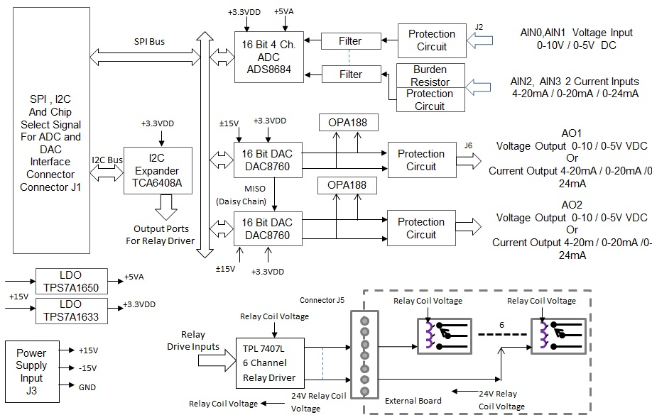
This solution shows how multiple different types of analog inputs and outputs can be managed effectively in common IED type applications on the smart grid. Not only can both current and voltage based signals be handled but also allow flexibility through configurability. In addition, this solution shows how high accuracy in signal detection is possible.
More information can be found here: TIDA-00310
