

In the last post in this series we discussed some of the charging architecture behind electric vehicles (EV), and laid some of the base work to figure out how these new vehicles can charge so quickly. Today we’re going to elaborate on the topic and start looking at the high power interface between the car and the grid.
In order to get enough power into an electric vehicle to provide reasonable charging times, we’re going to need some pretty serious equipment it seems. To help organize the different levels of power availability, the Society of Automotive Engineers (SAE) has categorized them for us:
|
Level |
Definition |
Energy Rating |
|
Alternating current (AC) energy to the vehicle's on-board charger; from the most common U.S. grounded household receptacle, commonly referred to as a 120 volt outlet. |
120 V AC; 16 A (= 1.92 kW) |
|
|
Alternating current energy to the vehicle's on-board charger; 208 - 240 volt, single phase. The maximum current specified is 32 amps (continuous) with a branch circuit breaker rated at 40 amps. |
208-240 V AC; |
|
|
Direct current (DC) energy from an off-board charger; there is no minimum energy requirement but the maximum current specified is 400 amps and 240 kW continuous power supplied. |
very high voltages (300-600 V DC); very high currents (hundreds of Amperes) |
In broad strokes, level 1 is essentially a standard U.S. power outlet, level 2 is a high current two or split phase outlet and level 3 is high voltage DC. While level three is very interesting to EV owners, since it provides the 20-30 minute charge times, level 1 and level 2 are more applicable since they are and will continue to be more pervasive.
Markets outside of North America have a slightly different categorization system which falls under the IEC61851 standard. It is split into four levels, all at 240 VAC (typical household voltages) and is defined by the amount of current supplied. The highest level, level four, is a high voltage DC system and is equivalent to the SAE level 3.
Hopefully this clears up what is meant when someone talks about levels of charging. It is really just how much power can be delivered and if it is AC or DC. However, this simple chart is far from the whole story. Let’s take a closer look at the ubiquitous AC chargers that are on the market today.
Electric vehicles are not a new thing in North America. They have come and gone in various incarnations since the 1880s but only recently have they gained enough popularity to garner significant standardization in charging protocol. In 2001, California (the North American leader in EV rollout) settled on the SAE J1772 standard for electrical connectors for EVs. The most recent incarnation of this standard is a large five pin plug that is capable of supplying the required power for both level 1 and level 2 charging. The five pins include AC line 1, AC line 2, ground, proximity detection and a control pilot line.
Essentially, the large conductors connect straight to the installed wiring when charging is enabled. The enabling of the charge voltage is what the other two lines are for. The proximity detection signal prevents the vehicle from moving when connected to a charging station. The pilot signal on the other hand is a bit more complex.
In order to charge safely, the vehicle needs to know how much power it is allowed to pull from the station (the service rating of the instillation) and the station needs to know the charging status from the car. Rather than use a full duplex serial link for this, which would complicate the connector, the charging station generates a 1 kHz square wave on the line. The duty cycle of this wave is measured by the car and correlates to a specific amperage. When plugged in, the car will now know not to pull more than the station is rated for.
To determine charge state, the vehicle adds a resistance to the pilot line, which will drop the voltage. This drop is then measured by the station and correlates to statuses such as vehicle detected, standby, ready to charge, ventilation active or an error. Once the station and the car have performed this basic handshake, the charge process is almost ready to begin.

The last piece that should occur is a Ground Fault Circuit Interrupter (GFCI) safety check. This is very similar to the outlets installed in North American kitchens. A GFCI fault occurs when there is current passing out of the system via another conductor, typically the ground line. This usually means that there is a short somewhere and power should be cut immediately. The charging station will constantly monitor for any GFCI faults and cut power to the vehicle if detected. Also just like the outlet, there is a simple test procedure to ensure that the sensor is working properly.
Since the North American grid is normally split phase 240 V, the J1772 connector is a simple solution. In other regions though, higher voltage and true two and three phase power is more common. To account for the various configurations of voltages available to the vehicle, these regions have a slightly different connector defined. The VDE-AR-E 2623-2-2 connector (or Type 2 for short) is a seven pin high current conductive charge coupler that is derived from the earlier IEC60309 standards.
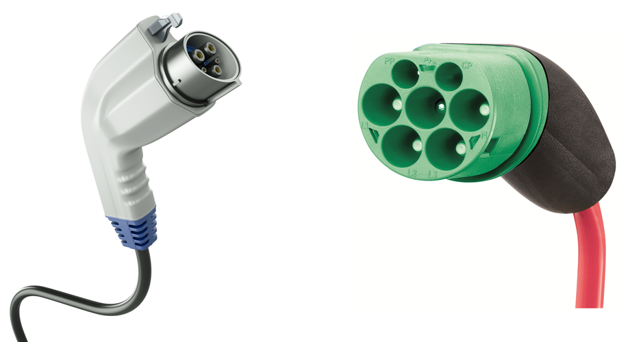
J1772 connector VDE-AR-ER 2623-2-2 connector (or Type 2 for short)
Type 2 has the additional signals which support the same kind of signaling that is present in the SAE J1772 specification, so the two do share a reasonable amount of interoperability to make global vehicle design and distribution easier. The Type 2 also includes support for three phase voltages however, which enables significantly more power at the same current levels as described earlier. This enables charge levels up to almost 44 kW, practically double the J1772 standard that is limited by the North American grid.
These AC standards cover power delivery from the grid to the vehicle up to about 20 kW in North America and about 40 kW in regions where the higher voltages are available. However it is very rare that installed service equipment is rated for the full 80 A that is allowed by the specification or that the vehicle can handle that much current. Regrettably, the vast majority of available chargers are actually limited to only 30 A. This gives a normal usable power rating of only about 7 kW in North America and 12 kW in other regions, which is a far cry from the current maximum the standard allows. To charge up a common EV battery with a capacity of 24 kWh, it still takes 2-3.5 hours on a good day. With ranges of only about 100 miles, this would over double the time it takes me to get from the TI office in Dallas to our Houston branch.
Even if we ignore the limitations of providing this power from the grid and assume the service line is a large as possible, the AC to DC converter that is required to charge the batteries is still in the vehicle itself. This creates some very hard limits on its capacity since all the components need to be automotive quality and the system is fairly space constrained. This is why some cars can only accept lower charge currents. It’s pretty easy to see that this converter can be a major bottleneck to high power charging.
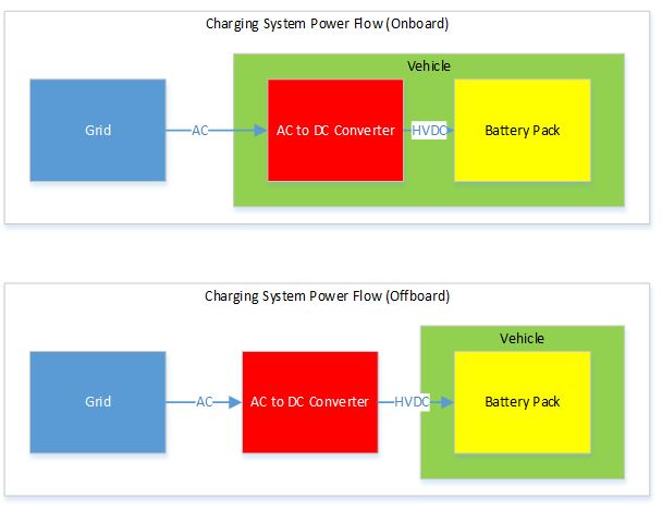
So, how are people getting 30 minute charges on these vehicles? The answer is DC fast charge, where the AC to DC converter is external to the car and able to handle much higher power levels. This is still an emerging standard, with several competing versions making things even more complicated than standard AC charging systems. This makes it a topic for another day.
Additional resources:
- Part 1: Untangling electric vehicle chargers - Getting started
- Part 3: Untangling electric vehicle chargers - Level 3
Easy-to-use TI Designs reference designs:
- Level 1 & 2 electric vehicle service equipment reference design.
- Bi-directional non-isolated buck-boost converter reference design.
- Two-phase interleaved power factor correction converter with power metering reference design.
- 230-V, 3.5-kW, high-efficiency, single-phase power factor regulator converter (PFC) design.
