

In part 1 of this blog series, I reviewed the wireless M (wM)-Bus protocol standard in the 868 MHz ISM band in Europe, while in part 2 I looked at wM-Bus N-modes and the European Telecommunications Standard Institute (ETSI) category 1 receiver performance. In part 3, I listed the pros and cons of a two-chip MSP430™ microcontroller (MCU) + CC1120 RF transceiver combo versus the latest single-chip wM-Bus subsystem using the SimpleLink™ Sub-1 GHz CC1310 wireless MCU.
Now on to part 4. Have you ever asked yourself one (or more) of the following questions?
- How can all of these battery-powered wM-Bus RF subsystems run for 10+ years on a single battery?
- How much battery capacity is inside a wM-Bus-enabled heat cost allocator (HCA) or a water meter to achieve this 10+ year lifetime?
- How is it possible to transmit at +500mW with a 169 MHz N-mode-capable gas meter from a battery supply?
In this installment of this blog series, I hope to provide you some of the answers you’ve been looking for!
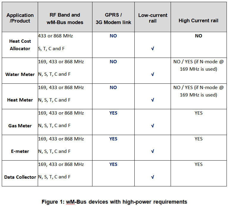
The ETSI 300 200 v2.4.1 document defines the applications, frequency bands and maximum equivalent isotropically radiated power (EIRP) for each ISM band or subband in the European Union’s (EU) Sub-1 GHz RF spectrum. Focusing on the smart grid relevant frequencies of 169, 433 and 868 MHz, you can summarize the requirements into two categories:
- 433MHz (F-mode) or proprietary with +10mW ERP (or +10dBm) and 868MHz (S1, S2, T1, T2 and C-mode meter) with +25mW ERP (or +14dBm) = “low current.”
- 169MHz (all N-modes) or 868MHz (C-mode data collector = other) with 500mW (or +27dBm) ERP = “high current.”
These two categories require separate approaches for the power supply because of the maximum currents required in each case. For the low-current case, typically 20-50mA at 3.0 or 3.6V is sufficient to power the RF device; newer devices like the CC1310 wireless MCU have highly efficient implementation and can deliver +14dBm with only 22.6mA at a 3.6V supply. The same transmit power is also available at 3.0V (and lower) power supply due to the integrated DC/DC switch inside the CC1310 solution.
The low-current rail typically supplies the MCU and the sensing portion, such as temperature or pressure measurement or rotation detection. The low-current voltage rail is really “low power,” as most of the sensing and standby currents are in the 2-10µA range (at 3.0 or 3.6V). Such low-power consumption is the prerequisite for achieving 10+ years of battery life. Obviously, tackling an RF current of 20-50mA is the biggest challenge, but luckily RF operations happen only periodically (from every 30s to a few times in 24 hours) so the resulting current consumption is in the range of few microamperes.
The high-current case must supply currents of 300-800mA or even up to 1A, especially for 169 MHz N-mode solutions, for several hundreds of milliseconds. Given the inherent inefficiency of 169 MHz antennas, which are small enough to fit into a gas-meter enclosure, losses of 6-10dB are common. In the 868MHz band, where C2-mode data collectors operate at 869.525 MHz, the integrated antennas are much more efficient; thus 450-500mA is sufficient for +27dBm (500mW) transmit power, as documented in this Sub-1 GHz CC1120 + CC1190 reference design.
Solving the low- and high-current challenge in battery-powered smart meters
Low-current smart-metering systems consist of HCAs, water and heat meters, and gas meters with +14dBm transmit power, as in wM-Bus S, T and C-modes.
HCAs are probably the simplest sub-metering devices on the market and have the lowest power budget: a few microamps on average. You can calculate the power budget using a simple spreadsheet with the timing for each mode (sleep, active with RF, inactive without RF but sensing temperature or infrared) and knowing the duty cycle of the application.
Typically, a 1Ah battery of 3.0 or 3.6V is sufficient for a 12-year 10 plus two year lifetime. This will strongly depend on the temperature profile of the HCA, where higher ambient temperatures (when the heater unit is radiating heat) diminish battery-life expectations. Still, with proper low-power software design, the 1Ah budget is sufficient, including battery self-discharge.
Water meters are slightly more demanding than HCAs, as they have to run rotation-detection tasks, which are often in the range of 2-6µA depending on the principle used. Next are heat meters, which are water meters with additional very high-precision temperature-difference measurements for the forward and backward flow. This measurement adds another few microamps of average current to the whole system budget. Water and heat meters commonly use a battery with 2.5Ah or similar capacity. Again, having a 3.6V battery will most likely necessitate a buffer capacitor in parallel, which can deliver the peak currents for RF operation. Sometimes, you can use LDOs and ultra-low-power DC/DC converters such as the TPS62730 or TPS62740, depending on if you need a specific voltage level to guarantee the measurement part of the system.
Gas meters (without 3G or a +27dBm wM-Bus RF subsystem) will have a similar power budget to heat meters, as they have to run also temperature and pressure sensing in addition to flow measurement.
High-current systems in smart metering include gas meters with 169 MHz N-mode wM-Bus, data collectors with N-mode or C2-mode support where +27dBm ERP is allowed, and often e-meters with data-collecting functions and C2 support (or GPRS/3G modem interface). These systems in fact have both low- and high-current rails inside: metrology and application and RF with <=+14dBm are in the low-current rail. The high-current rail is enabled only for the transmit operation in wM-Bus or for 3G communication. Typical battery capacities used in gas meters are 19Ah with 3.6V and a hybrid layer capacitor (HLC), but 3.0V lithium manganese dioxide (LiMnO2) primary cells in series, in parallel or both configurations are gaining traction due to their inherent pulse-load durability and other advantages.
The traditional approach has been to use a 3.6V lithium thionyl chloride (LiSoCl2) battery and back that up with an HLC. The HLC takes care of the current-load pulses, which can go up to 2A in the case of a 3G modem.
You will need another approach if using 3.0V LiMnO2 batteries – these can sustain the peak current without a buffer cap or HLC but may not deliver the 3.3V, 3.6 V or even higher voltage required for the 3G modem or wM-Bus N-mode power amplifier. In such cases, you can use either a buck-boost topology or two batteries in series to achieve a nominal 6V voltage, which then gets downconverted to 3.3 or 3.6V for the high-current rail and often 2.1 or 1.8V for the low-current rail.
As one-size-fits-all strategy does not work in smart meters; I recommended working with TI power and system experts to find the best solution for each specific application. Future reference designs will incorporate the latest power-management technology from TI to achieve more power-efficient and cost-competitive solutions for the next generation of RF-enabled smart meters and data collectors.
Additional resources
- Check out these TI Designs reference designs:
- Get started developing with Sub-1 GHz with the new CC1310 LaunchPad™ development kit
- See the entire European smart grid RF communications in Sub-1 GHz blog series.
