

Have you noticed?...it’s rare to find new generation op amps and other ICs in DIPs (dual-inline packages). Without volume demand, it’s not economically viable to offer new ICs in DIPs. Breadboarding with these newer fine-pitch micro-packages can be a pain. What to do?
This DIP adapter kit eases the pain. For ten bucks you can mount SO-8, SOT23 (3, 5, 6, or 8-lead) MSOP-8, SC70-6, SOT563-6 packages. We won’t make a dime on these adapters—we’re just trying to make it easier to design with these tiny packages. In fact, you are welcome to the CAD layouts to modify and/or fabricate yourself. You can optimize the assortment to concentrate on the package types you use most frequently. Yes, I know, it takes a steady hand to hand solder these ICs but you can do it. Then use them in breadboards like DIPs.

We have other breadboarding circuit boards you may find useful:
- Universal EVM for SOT23, MSOP, SO-8—four layouts with a small breadboarding area.
- Similar to above but for op amps with shutdown pin.
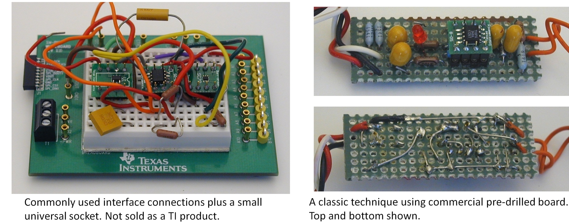
We all have our favorite breadboarding methods. I frequently use a white universal socket for quick checks of device behavior. These convenient boards are abhorred by many analog experts. They should be used with caution as they add capacitance between adjacent contact rows that can alter circuit performance. The key is awareness. Sensitive nodes can be air-wired while using the plug board for less sensitive portions of the circuit. Some high speed or sensitive circuits just don’t belong on these boards so use good judgment. High speed is not generally my territory so I get along pretty well with them.
The time-honored “parts ball” approach is functionally great—low capacitance and low leakage. A blob of air-wired components can be supported by a universal layout PCB used for some connections or a solid copper PBC for a ground plane and support. You’ve probably seen pictures of analog icon Bob Pease using this approach. It can be more difficult to make changes or repairs and it tends to be a solo gig. It’s difficult for a colleague to use, trace or modify. They can quickly grow into a fragile, three-dimensional mess that even the creator is challenged to decode.
With thoughtful design and circuit simulation, many of us proceed directly to a prototype circuit board design. If you are working with relatively familiar components and circuit techniques, the risk of major changes is probably low. Still, there are many times when hands-on experimentation and optimization are required. I made a sweep through our applications lab and collected a few potentially useful breadboarding and prototyping ideas. Check them out here.
It’s your turn… please send me pictures of your breadboarding techniques—your best (or your maybe your worst, just for fun). I’ll add them to this collection and we can all learn!
Tune in next week for a special holiday brain teaser. Comments welcome and thanks for reading,
Bruce email: thesignal@list.ti.com (Email for pictures, ideas, direct communications.)
Table of Contents for all The Signal blogs.

