

In a previous blog on supply bypassing, I cautioned that poor bypassing could increase distortion of an amplifier. A reader, Walter, asked an interesting question… where should you connect the ground of a bypass capacitor to avoid problems?
This raises questions regarding proper grounding techniques. Wow. Big topic, but I may be able provide some insight with a couple of simple examples.
Figure 1 shows inverting and non-inverting amplifier stages with unintended, parasitic resistance or inductance in the ground connections (highlighted in red). The nodes A, B and C are all intended to be ground. But if current flows in parasitic ground impedances, these nodes will not be at the same potential. It is these parasitic ground impedances that can allow distorted ground currents to contaminate signals.
Walter’s specific question was, “where should you connect the bypass capacitor [the ground side].” It’s an important point. The currents flowing in op amp supply terminals (and therefore the bypass capacitors) may be distorted because they represent only half a sine wave. If distorted (or other interfering) current flows into a vulnerable ground node it can increase the distortion (or other errors) of the amplifier.
An interfering or distorted current flowing into node_A directly affects the ground reference of the input signal, summing in an error. Likewise, a ground current injected into node_B serves as a direct input to the amplifier stage (inverted, in the first circuit). Ground current flowing into node_C directly sums an error with the output voltage. This node may be less vulnerable because the error signal is not amplified by the circuit gain.
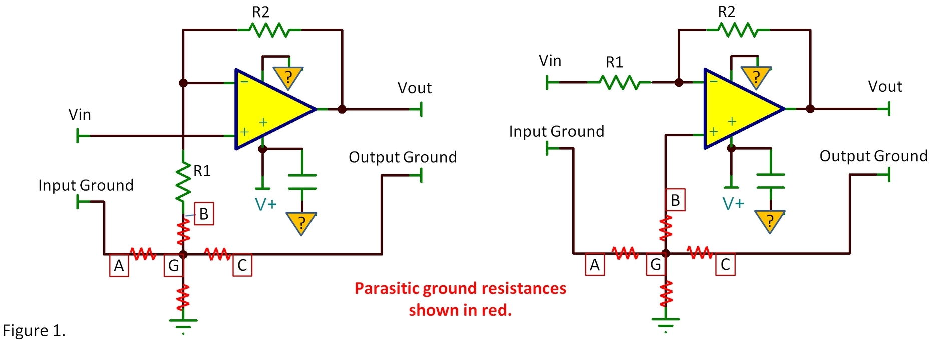
The bypass capacitor should be connected to node_G. Though there may be additional parasitic impedance on its way to other ground points, variation in voltage at node_G affects the critical nodes equally, so it does not inject an error or distortion. I’ve shown an op amp with a single power supply. The ground connection of the op amp (shown on top of the op amp) should also connect to Node_G. A dual (±) supply op amp circuit would have another bypass capacitor for the negative supply and it, too, should connect to node_G.
A solution is to create a circuit board that establishes a ground with the characteristics of node_G. The principle is simple—the circuit trace from the input ground terminal to the ground side of R1 should be a clear path with no connections to contaminating sources of current along the way (figure 2). This input ground trace can join a larger ground connection or ground plane where they meet. With some gain in this stage, output errors are less critical, but you still may want a separate trace to the output terminal connections.

The input ground connection should not connect to equipment chassis at an input connector. This would create an opportunity for other interfering ground noise (such as AC mains ground currents) from impressing current on the clean input ground trace.
A single blog cannot begin to cover all the issues relating to the art of grounding. Woops… did I call this an “art?” It’s science, not art! While, at times, may seem like black magic, Ohm’s law is always at work. Considering where ground currents flow and how they could affect the circuit is always a good start!
Thanks for reading. Comments welcome below,
Bruce


