

SPICE is a useful tool to help check for potential circuit stability problems. Here is one simple way to do it:
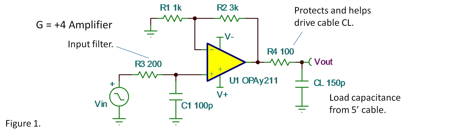
Figure 1 shows a non-inverting amplifier using the OPA211 with a couple of minor variations that are common in many applications. R3-C1 is an input filter. R4 is an output resistor to protect against abuse when connected to the outside world. CL models a five-foot cable.
Checking the response to a small-signal step function or square wave is the quickest and easiest way to look for possible stability problems. Figure 2 shows the simulation circuit. Notice that the input terminal is connected to ground and the input test signal is connected directly to the non-inverting input. The input filter would slow the input edge of a step function. If you want to know how a bell rings, hit it with a hammer, not a rubber mallet.
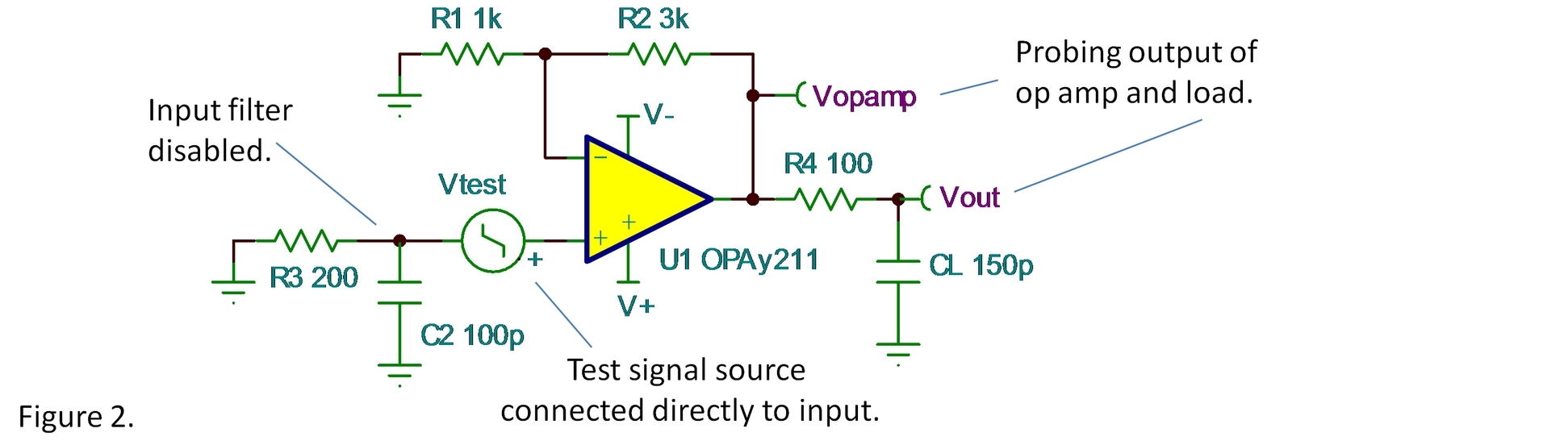
The response is probed at the output of the op amp, not just the Vout node of the circuit. R4 and CL filter the output response so that Vout will not show the true overshoot of the op amp. To check stability, we want to know what the op amp is doing.
Notice that the amplitude of the applied step is 1mV (creating a 4mV step at the output). We want the small-signal step response. A large input step that induces slewing will have less overshoot and will not clearly reveal potential instability.

The simulation shows approximately 27% overshoot at the op amp’s output, too much to be comfortable that this circuit will be stable under all conditions. Assuming a second-order stability system, this would indicate a phase margin of approximately 38°. Also, notice that the frequency response shows considerable amplitude peaking, another sign of potential instability. The peaking occurs at 14MHz, the inverse of the period of the ringing in the time domain. A commonly accepted guideline for reasonable stability is a phase margin of 45° (or greater) which translates to 20% (or less) overshoot.

There are fancier analyses that can be done with SPICE—Bode analysis by breaking the loop, finding phase and gain margins. But for most relatively simple circuits (feedback loop involving one op amp) this approach is a very good indicator of possible problems. Of course, any SPICE simulation relies on the accuracy of the op amp’s macro model. Our best SPICE models are excellent but not perfect. Furthermore, circuit variation, non-ideal components, circuit board layout parasitics, poor supply bypassing—all can affect the circuit. That’s why you build it, test it, compare with simulation and optimize. SPICE is a useful tool, valuable but not sufficient.
How would you improve the stability of this circuit? Comments welcome below below…
Thanks for reading,
Bruce thesignal@list.ti.com
Simulations are performed with the free version of TINA-TI.
Index to all The Signal blogs.
-

Stephen Power
-
Cancel
-
Up
0
Down
-
-
Reply
-
More
-
Cancel
Comment-

Stephen Power
-
Cancel
-
Up
0
Down
-
-
Reply
-
More
-
Cancel
Children