

Designers sometimes find op amp data sheet specifications perplexing because not all performance characteristics have minimum or maximum specifications. You must occasionally rely on “typical” values in the specification table or typical performance graphs. But what does typical mean? How much can it vary?
There are no easy answers and it depends on the specification. Here are some guidelines on three characteristics which seem to get frequent questions:
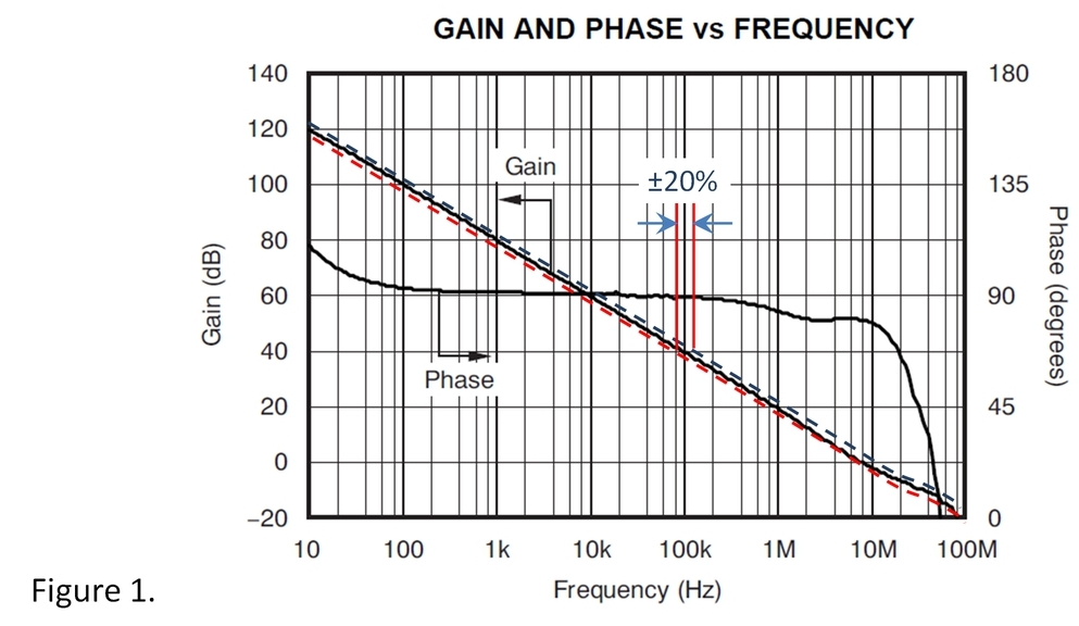
Bandwidth—The gain-bandwidth product (GBW) of an op amp is primarily controlled by the current in the input stage and the on-chip capacitance values. The variance of these two variables could mean that GBW could vary by ±20% or so. While this might sound like a wide range, it’s generally pretty easy to design with ample GBW by selecting an op amp with sufficient margin. The closed-loop bandwidth of your application can be controlled with feedback components, if necessary. Notice that on an open-loop gain/phase graph (figure1) this variation appears remarkably small.
Slew Rate is affected by the same variables as bandwidth, internal currents and capacitance and the same issues apply. Op amp selection of 20% faster than your minimum needs will usually suffice. Perhaps you might want a bit more margin in critical applications. Most applications do not push amplifiers near their slew limit so this is not often an issue.
Voltage Noise—Broadband or flatband voltage noise of amplifiers depends primarily on the current in the input stage transistor(s). Higher current reduces the noise in a square-root relationship. So a 20% variation in current makes approximately a 10% change in flatband noise density (figure2).

Low frequency 1/f noise (also called flicker noise) is a different matter and can vary much more. The noise amplitude in the 1/f region can vary over approximately a 3:1 range. A somewhat larger variation might be expected in JFET and CMOS processes. This noise region determines the peak-to-peak noise in low frequency band, often specified from 0.1 to 10Hz. So this noise spec can also vary over a similar range.
These are reasonable guidelines but there is no way to account for the wide range of amplifier designs and IC processes used. But some information is better than none and most designs can comfortably tolerate these estimated variations.
The margins appropriate for your application may vary according to the type of equipment you are designing, and, perhaps, the end-product testing you perform. The consequences of a marginal miss on a spec can affect the margins you design to. This engineering judgment is an important factor in good analog design. If you need guidance on a particular situation, you are welcome to ask for more information. Our E2E forums are the place to do it. We may be able to provide some additional information or estimates.
Are there other typical specs give you grief? If so, I’d like to hear about it. Your feedback might actually influence how we specify our next IC.
Thanks for reading and your comments are welcome.
Bruce
-

Bruce Trump
-
Cancel
-
Up
0
Down
-
-
Reply
-
More
-
Cancel
Comment-

Bruce Trump
-
Cancel
-
Up
0
Down
-
-
Reply
-
More
-
Cancel
Children