
The power of a GUI simplifies the design of digital power factor correction
When looking at power conversion systems that can take advantage of digital control techniques, it is obvious and expected to look for power factor correction (PFC) systems. The control loops are typically running at quicker speeds to accommodate the faster switching frequency of the PFC power stage.
Texas Instruments has designed a digitally controlled 2-Phase Interleaved Power Factor Correction (ILPFC) converter that can now be used to develop PFC control software from a GUI based tool. This kit is based on a single C2000™ TMS320F28035 microcontroller (MCU) and controls a 700W interleaved PFC power stage. This kit is a reference design that can be modified to meet custom PFC system requirements. That is where the powerSUITE tools come in.
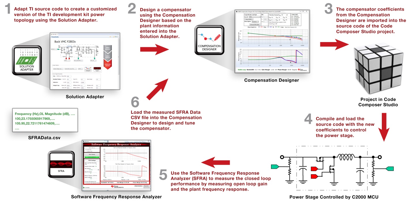
The powerSUITE digital power software tools allow you to modify a few PFC design parameters from the GUI and generate the PFC control code in order to match your PFC system requirements. If your design requires the use of different input or output voltages, different power stage component values, different digital compensators or a single-phase PFC topology, you can change these parameters on the Solution Adapter GUI.
The values from the Solution Adapter GUI are used by the PFC power stage model in the Compensation Designer to plot the theoretical loop gain (voltage and current loops) Bode plot for your custom PFC power stage board. You can then modify the compensator values from this GUI to achieve the desired loop (voltage and current loops) bandwidth, gain margin, and phase margin.
These theoretical values generated by the Compensation Designer can then be validated against the results from the Software Frequency Response Analyzer (SFRA). The data plotted by the SFRA is measured and calculated using the available processing capability in the C2000 MCU. This means that the frequency response is measured entirely in software on the MCU and then digitally transferred to the PC for viewing. However, this data could also be stored and analyzed by the MCU for on-chip system analysis. Once the actual frequency response has been measured and transmitted back to the PC running TI’s Code Composer Studio™ integrated development environment, the measured values of the plant are used by the Compensation Designer to provide a more accurate, measurement-based Bode plot that can be used to more finely-tune the digital compensator to achieve the desired bandwidth, gain margin, and phase margin.
Why not try out this simplified design process yourself? Download the free powerSUITE digital power design tools and start adapting the software for your own PFC design!
Login to your myTI account to leave a comment below with ways you can use the powerSUITE tools in your next design.
