

Last week we looked at the source of input bias current in CMOS and JFET amplifiers, finding that it comes from the leakage of one or more reverse-biased P-N junctions. Check it out if you missed it. We ended with a caution that these leakages increase significantly with temperature.
The reverse-biased leakage of a P-N junction has a strong positive temperature coefficient, approximately doubling for each 10°C increment in temperature. This exponential increase racks up quickly as shown in the normalized graph of figure 1. At 125°C leakage climbs to approximately 1000-times the room temperature value.
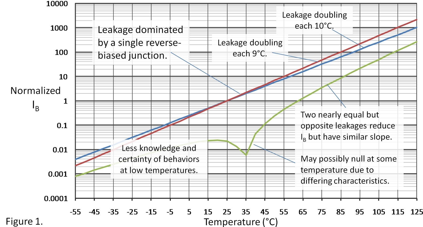
The rate of increase can vary with diode characteristics and the doubling of current may occur over a range of 8°C to 11°C, or so. This increased bias current at high temperature can be a significant problem in some circuits and may a good reason to select a FET or CMOS op amp with a very low room-temperature input bias current. In some cases you may achieve lower IB at high temperature with a bipolar-input (BJT) op amp that does not have such a dramatic increase at high temperature (a good topic for another blog).
We generally assume that the leakage continues to fall at lower temperatures but other possible sources of leakage may alter the behavior. These stray leakages may have different temperature dependency. To be honest, less is known about the behavior below room temperature because the higher leakage at room temperature and above is the greater concern. It’s best not to place high confidence in behavior much below room temperature. The important issue at low temperature is more likely to be possible water condensation which can cause leakage to rocket upward.
As discussed last week, the input bias current of most CMOS op amps comes from the difference in leakage of two input clamp diodes connected to the power rails. In a perfectly balanced world, the residual difference between two nearly equal leakages still has the same exponential temperature variation, it just starts at a lower initial value. The polarity of IB is uncertain and with small differences in diode behavior, the net current may dip through zero at some temperature (the logarithmic graph shows the absolute value without sign).
So… what to conclude? If very low input bias current is critical in your FET op amp circuit, carefully consider its increase with temperature. Study all the specifications and typical performance graphs. Avoid placing sensitive circuitry near heat sources. Make your own measurements, if necessary. For really critical applications, there are special-purpose amplifiers with ultra low input bias current. They use creative protection circuitry unique pinouts to achieve IB in the range of 3fA at room temperature—three orders of magnitude lower than general purpose devices. Examples:
- LMP7721— 3fA Input Bias Current CMOS Op amp
- INA116—Ultra-Low Input Bias Current Instrumentation Amplifier
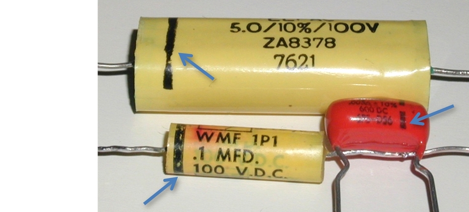
And now, a totally unrelated Random Quiz. Please, no TI peeps allowed. On the film capacitors below, what is the meaning and purpose of the black bands?
Thanks for reading and comments welcome,
Bruce email: thesignal@list.ti.com (Email for direct communications. Comments for all, below.)
Index to all The Signal blogs.

