This thread has been locked.

If you have a related question, please click the "Ask a related question" button in the top right corner. The newly created question will be automatically linked to this question.

UCC37324: Duty Cycle

Part Number: UCC37324

Hi,

Good Day.

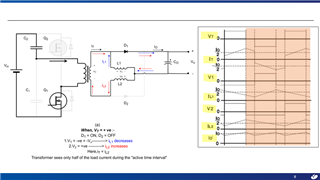
For calculating the ripple in individual inductor of current doubler rectifier, as shown in the below image, 'D' is used. As specified in the app note, this D is the duty cycle defined as the total positive and negative power transfer duty cycle.

Customer did not understand this step. Because he think time corresponding to peak-to-peak ripple must be either only positive or negative power transfer duty cycle (refer second image.) But then when he calculated with this logic the 'K' calculated by him comes out to wrong.

Please advise. Thank you very much.

slua323 Current Doubler Rectifier Offers Ripple Current,2004 by Steve Mappus.pdf

Best Regards,

Ray Vincent

  • Hello Ray,

    Thanks for reaching out!

    -------

    I am not sure I understand your question... Could you please tell me what the customer's issue is?  Does the customer not understand the peak inductor current equation?

    Thanks,

    Aaron

  • Hi Aaron,

    Good Day. It is about the duty cycle formula. We all know that the duty cycle is the fraction of one period in which a signal or system is active. But on the SLUA323 note, duty cycle defined as the total positive and negative power transfer duty cycle. That's why the customer is confused when it comes the duty cycle on the SLUA323 note. He thinks time corresponding to peak-to-peak ripple must be either only positive or negative power transfer duty cycle.

    Best Regards,

    Ray Vincent

  • Ray,

    I would look at this application note too:  https://www.ti.com/lit/an/slua121/slua121.pdf

    And the duty cycle is phrased that way because you are pushing and pulling on the transformer with a turns ratio.  That's why the duty cycle is limited to 50% by the "2" in the "2 X N".  During one active period there is a "positive push" and during another, the is a "negative pull" on the transformer.  (seen on the secondary).

    Please let me know if this helps.

    Thanks,

    Aaron

  • Hi Aaron,

    Good Day. Please see below the response of our customer to your reply. Thank you very much.

    I studied the shared application note.

    I understood that though ‘D’ is defined as the total positive and negative power transfer duty cycle, in the equation 1 (image attached below), the ‘2’ at the denominator balances the equation.

    But, my doubt is, how in equation 2 (image attached below) D is considered, instead of ‘D/2’.

    I am getting this doubt as I think , the ripple in the individual inductor (L2 in the attached image) will be in either in the positive power transfer interval or negative power transfer interval i.e. ‘D/2’ according our convention. Please refer to below image (Here I have considered Half Bridge on the primary side but ripple in individual inductor will be of same nature in push-pull too.)

    Best Regards,

    Ray Vincent

  • Hello Ray,

    They should solve for D in equation 1 and plug it into equation 2.

    -------

    Please let me know if that helps.

    Thanks!

    Aaron