Part Number: CC2640R2F
Other Parts Discussed in Thread: CC2652RB, , LAUNCHXL-CC2640R2
i2cDeviceReadReg8 Am i using this function correctly
Prototype: i2cDeviceReadReg8(#i2cAddr, regAddr8; value8)
Reads an 8-bit value from a register with 8-bit address in an I2C device.
This is equivaluent to the following sequence:
- Start condition (i2cStart(), status bits not cleared)
- Transmit I2C address + W (i2cTx())
- Transmit 8-bit register address (i2cTx())
- If successful:
- Repeated start condition (i2cRepeatedStart())
- Transmit I2C address + R (i2cTx())
- Receive 8-bit register value (i2cRxNack())
- Stop condition (i2cStop())
Parameter value(s)
- #i2cAddr: I2C slave 7-bit address, shifted left one bit ([7:1] = address, [0] = zero)
- regAddr8: Register address
Return value(s)
- value8: Register value
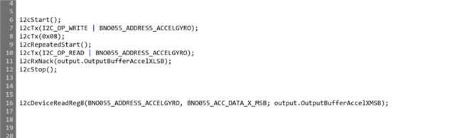
Below I believe it should send the device address, read the register address and then storage the third variable as the read value to the output to be read in the main programme
i2cDeviceReadReg8(BNO055_ADDRESS_ACCELGYRO,BNO055_ACC_DATA_X_LSB; output.OutputBufferAccelXLSB);
U16 eco1;
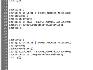
i2cDeviceReadReg8(BNO055_ADDRESS_ACCELGYRO, 0x05; eco1 );
output.OutputBufferAccelZLSB = eco1;
// Schedule the next execution
fwScheduleTask(1);
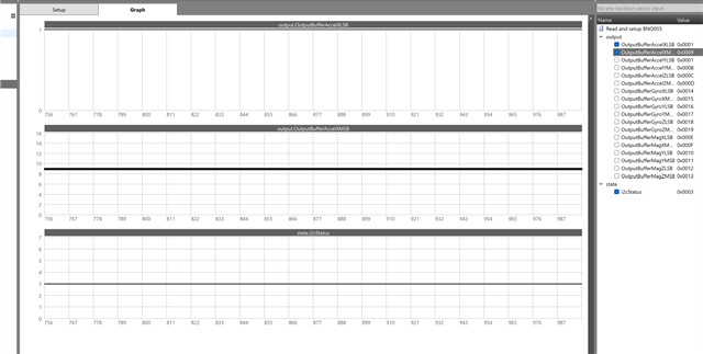
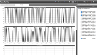
Both of the above functions pass the second variable through from the sensor controller ram, rather than the value that is supposed to be read into the third variable and passed on into the output, what am I doing wrong?
DataReadSensorController[0] = scifTaskData.readAndSetupBno055.output.OutputBufferAccelXLSB;
DataReadSensorController[1] = scifTaskData.readAndSetupBno055.output.OutputBufferAccelXMSB;
DataReadSensorController[2] = scifTaskData.readAndSetupBno055.output.OutputBufferAccelYLSB;
DataReadSensorController[3] = scifTaskData.readAndSetupBno055.output.OutputBufferAccelYMSB;
So for instance for the second function function is being read as 0x05 rather than the value within that register