This thread has been locked.

If you have a related question, please click the "Ask a related question" button in the top right corner. The newly created question will be automatically linked to this question.

TLV320AIC3262: Audio recording through headphone mic (TLV320AIC3262)

Part Number: TLV320AIC3262


Hi..

We are using TLV320aic3262 codec in our platform.

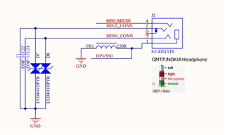
We want to record live audio through headphone mic, Could you please let us know which register's need to configure for this.

Thanks very much

Rizwan Chikodi

  • Hello Rizwan,

    Thank you for reaching out. The answer to your question is highly dependent on your application. Please consult the TLV320AIC3262 datasheet and TLV320AIC3262 Applications Reference Guide for information on how to configure the device for your application.

    The reference guide contains detailed information on device initialization (section 3) and example scripts for common applications. Please see 4.6 Recording and Voice Setup Scripts and try one that most closely fits your application.

    Sections 10.3.4.4 Using the Headphone Amplifier and 10.3.5 ADC / Digital Microphone Interface of the datasheet are also helpful. 

    Best,
    Andrew

  • Hi Andrew Jackiw

    We have set codec register using attached script for audio recording.

    #########################################
    #codec-18.sh 
    #########################################
    #Software reset
    i2cset -f -y 2 0x19 0x0 0x0
    i2cset -f -y 2 0x19 0x7f 0x0
    i2cset -f -y 2 0x19 0x1 0x1
    
    #clock configuration(same for asi1 & as2)
    i2cset -f -y 2 0x19 0x0 0x0
    i2cset -f -y 2 0x19 0x4 0x0 # DAC_CLKIN=ADC_CLKIN=MCLK1
    i2cset -f -y 2 0x19 0xb 0x81 # NDAC powered and NDAC=1
    i2cset -f -y 2 0x19 0xc 0x82 # MDAC powered and MDAC=2
    i2cset -f -y 2 0x19 0xd 0x00 # 
    i2cset -f -y 2 0x19 0xe 0x80 # DOSR=128
    
    i2cset -f -y 2 0x19 0x12 0x81 # NADC powered and NADC=1
    i2cset -f -y 2 0x19 0x13 0x82 # MADC powered and MADC=2
    i2cset -f -y 2 0x19 0x14 0x80 # AOSR=128
    
    #power & analog configuration
    i2cset -f -y 2 0x19 0x0 0x1
    i2cset -f -y 2 0x19 0x1 0x0
    i2cset -f -y 2 0x19 0x7a 0x1 # Ref power up delay
    i2cset -f -y 2 0x19 0x79 0x33 # ref charging time 1.1ms
    
    #audio serial interface routing configuration for ASI1
    i2cset -f -y 2 0x19 0x0 0x4 
    i2cset -f -y 2 0x19 0x1 0x00 # ASI1=I2S, 16 bits
    i2cset -f -y 2 0x19 0x8 0xf0 # ASI1 Left and Right DAC mixed of Left and Right data
    i2cset -f -y 2 0x19 0xa 0x00 # Master mode 
    
    #signal processing setting
    i2cset -f -y 2 0x19 0x0 0x0
    i2cset -f -y 2 0x19 0x3c 0x1 # PRB_P1
    i2cset -f -y 2 0x19 0x3d 0x1 # PRB_R1
    
    
    #output channel configuration
    i2cset -f -y 2 0x19 0x0 0x1
    i2cset -f -y 2 0x19 0x3 0x0 # Left DAC in PTM_P3_P4
    i2cset -f -y 2 0x19 0x4 0x0 # Right DAC in PTM_P3_P4
    i2cset -f -y 2 0x19 0x1b 0x30 # Left DAC to HPL and Right DAC to HPR and powered down
    
    i2cset -f -y 2 0x19 0x0 0x0
    i2cset -f -y 2 0x19 0x3f 0xc0 # Left and Right DAC powered up
    
    i2cset -f -y 2 0x19 0x0 0x1
    i2cset -f -y 2 0x19 0x1f 0xb9 # HP Ground_Centered and HPL volume is muted
    i2cset -f -y 2 0x19 0x20 0xb9 # HPR=HPL and HPR volume is muted
    
    i2cset -f -y 2 0x19 0x21 0x28 # CP clock divide=4 default
    i2cset -f -y 2 0x19 0x22 0x3e # CP default
    i2cset -f -y 2 0x19 0x23 0x30 # CP auto power up
    i2cset -f -y 2 0x19 0x1f 0x80 # HP Ground_Centered and volume is 0dB
    i2cset -f -y 2 0x19 0x20 0x80 # HPR=HPL and HPR volume is 0dB
    
    i2cset -f -y 2 0x19 0x0 0x0
    i2cset -f -y 2 0x19 0x40 0x40 # Left and Right DAC not muted
    
    i2cset -f -y 2 0x19 0x0 0x1
    i2cset -f -y 2 0x19 0x09 0x70 # HP 25%
    i2cset -f -y 2 0x19 0x1b 0x33 # Left DAC to HPL and Right DAC to HPR and powered up
    
    i2cset -f -y 2 0x19 0x0 0x1
    i2cset -f -y 2 0x19 0x09 0x10 # HP 100%
    
    #adc config
    i2cset -f -y 2 0x19 0x0 0x1
    i2cset -f -y 2 0x19 0x8 0x0 # VOCM= Input CM
    i2cset -f -y 2 0x19 0x34 0x20 # IN2L P-Term 20K on Left_ADC
    i2cset -f -y 2 0x19 0x36 0x80 # CM 20K on M-Term on Left_ADC
    i2cset -f -y 2 0x19 0x37 0x20 # IN2R P-Term 20K on Right_ADC
    i2cset -f -y 2 0x19 0x39 0x80 # CM 20K on M-Term on Right_ADC
    i2cset -f -y 2 0x19 0x3b 0x0c # Left_ADC enabled with 6dB
    i2cset -f -y 2 0x19 0x3c 0x0c # Right_ADC enabled with 6dB
    i2cset -f -y 2 0x19 0x3d 0x0 # Default ADC PowerTune
    
    i2cset -f -y 2 0x19 0x0 0x0
    i2cset -f -y 2 0x19 0x51 0xc0 # Left and Right ADC powered up
    i2cset -f -y 2 0x19 0x52 0x0 # Left and Right ADC not muted

    While recording through headphone mic we are getting only noise while playing audio recorded file.

    Is there any other register also needs to be configured in this for headphone mic recording ?

    Thanks and Regards

    Rizwan Chikodi

  • Rizwan,

    Please let me know your MCLK, BCLK, WCLK, and if you are trying to run the in master/slave mode. As well as if you used a test script to create this I2C file.

  • Hi Andrew

    We are able to see the BCLK, WCLK and MCLK  wave forms (In Slave mode ) on scope.

    1: J3 port support both input and output. And we are able to do playback successfully through J3 port [With Downloaded audio file],when capturing audio through J3 port and playing the same it only gives noise.

    2: The script we are taken from the TLV3262 application reference manual, we are using i2c command to set codec register's and script we run once the codec is up {on linux prompt}.

    Thanks very much

  • Rizwan,

    Thank you for the information. To be more specific, please let me know the specific values of BCLK, WCLK and MCLK that you are trying to set. Judging from your previous post, the TLV320AIC3262 is in slave mode and MCLK = 12.288 MHz, BCLK = 3.072 MHz, WCLK = 48 kHz are the clock settings. Can you confirm my understanding is correct?

    I am also assuming that one of the scripts in 4.6 Recording and Voice Setup Scripts of the reference guide is being used to set the I2C commands. Which script is being used in your application?

    Answers to these question will help further troubleshooting.

    Best,
    Andrew

  • Yes Andrew, your understanding is right.

  • Rizwan,

    Can you point me to which specific script from 4.6 Recording and Voice Setup Scripts section of the reference guide is being used to set the I2C commands? 

    There are a few options in this section. Which script is being used in your application?

  • Input register i have took from 4.6.1 and 4.6.2

    4.6.1 Stereo ADC with 48ksps Sample Rate and High Performance

    4.6.2 Stereo ADC with 48ksps Sample Rate and Low Power.

  • Rizwan,

    Thank you for the information. Please allow me a few days to look through your configuration in detail.

  • Hello Rizwan,

    Thank you for waiting. Everything appears to be correct for the most part. Here are some comments on your script above.

    • Please move '#power & analog configuration' block to be directly after the '#Software reset' block
    • In '#clock configuration (same for asi1 & as2) power both "NDAC/NADC" before "MDAC/MADC"
    • Move '#output channel configuration' to last block

    If these steps do not fix your issue, then there may be some more configuration needed to set up the headset. Please see 2.13.2 Headset Detection section of the reference guide as well as example script 4.6.3 Cellular Headset.

    Best,
    Andrew

  • Hello Andrew Jackiw

    Thanks for the response 

    I will check this configurations as you suggested and let you know the updates as soon as possible.

    Thanks & Regards

    Rizwan Chikodi

  • Hi Andrew Jackiw

    Thank you for the support.

    I'm able record through J3 port using 4.6.3 script.

    #########################################################################################
    # 4.6.3  Cellular Headset - Stereo Headphone with Mono External Microphone, 8kHz
    #########################################################################################
    # Software Reset
    #########################################################################################
    i2cset -f -y 2 0x18 0x00 0x00	# Initialize to Page 0
    i2cset -f -y 2 0x18 0x7f 0x00	# Initialize to Book 0
    i2cset -f -y 2 0x18 0x01 0x01	# Initialize the device through software reset
    #########################################################################################
    # Power and Analog Configuration
    #########################################################################################
    i2cset -f -y 2 0x18 0x00 0x01	# Select Page 1
    i2cset -f -y 2 0x18 0x01 0x00	# Disable weak AVDD to DVDD connection, make analog supplies available
    i2cset -f -y 2 0x18 0x7a 0x01	# REF charging time = 40ms
    i2cset -f -y 2 0x18 0x79 0x33	# Set the quick charge of input coupling cap for analog input
    #########################################################################################
    # Clock configuration
    # MCLK = 4.096 MHz, BCLK = 512 kHz, WCLK = 8 kHz (slave)
    #########################################################################################
    i2cset -f -y 2 0x18 0x00 0x00	# Select Page 0
    i2cset -f -y 2 0x18 0x04 0x33	# Set ADC_CLKIN = PLL_CLK and DAC_CLKIN = PLL_CLK
    i2cset -f -y 2 0x18 0x05 0x00	# Set PLL_CLKIN = MCLK1
    i2cset -f -y 2 0x18 0x06 0x91	# PLL settings: P=1, R=1
    i2cset -f -y 2 0x18 0x07 0x18	# PLL settings: P=1, R=1, J=24
    i2cset -f -y 2 0x18 0x08 0x00	# D=0000 (MSB)
    i2cset -f -y 2 0x18 0x09 0x00	# D=0000 (LSB)
    
    i2cset -f -y 2 0x18 0x0b 0x82	# NDAC = 2, divider powered off
    i2cset -f -y 2 0x18 0x0c 0x88	# DAC Power MDAC = 8
    i2cset -f -y 2 0x18 0x0d 0x03	# DOSR = 768 (MSB)
    i2cset -f -y 2 0x18 0x0e 0x00	# DOSR = 768 (LSB)
    
    i2cset -f -y 2 0x18 0x12 0x02	# NADC Powerdown NADC=2
    i2cset -f -y 2 0x18 0x13 0xb0	# NADC Powerup, MADC=48
    i2cset -f -y 2 0x18 0x14 0x80	# AOSR = 128
    
    #########################################################################################
    # Audio Serial Interface Routing Configuration - Audio Serial Interface #1
    # ASI #1 recording
    #########################################################################################
    i2cset -f -y 2 0x18 0x00 0x04	# Select Page 4
    i2cset -f -y 2 0x18 0x01 0x00	# Audio Serial Interface #1 is set to I2S mode, 16-bit
    i2cset -f -y 2 0x18 0x0a 0x00	# Route ASI#1 WCLK and BCLK to WCLK1 pin and BCLK1 pin
    
    #########################################################################################
    # Signal Processing Settings
    #########################################################################################
    i2cset -f -y 2 0x18 0x00 0x00	# Select Page 0
    i2cset -f -y 2 0x18 0x3c 0x01	# Set the DAC PRB Mode to PRB_P1
    i2cset -f -y 2 0x18 0x3d 0x01	# Set the ADC PRB Mode to PRB_R1
    #########################################################################################
    # ADC Input Channel Configuration --- IN1L
    #########################################################################################
    i2cset -f -y 2 0x18 0x00 0x01	# Select Page 1
    i2cset -f -y 2 0x18 0x08 0x00	# Set the input common mode to 0.9V
    i2cset -f -y 2 0x18 0x33 0x40	# Mic Bias enabled, Source = Avdd, 1.62V
    i2cset -f -y 2 0x18 0x34 0x80	# Route IN1L and CM1 to LEFT ADCPGA with 20K input impedance
    i2cset -f -y 2 0x18 0x36 0x80
    i2cset -f -y 2 0x18 0x3B 0x3C	# Left Channel Analog ADC PGA = 30 dB
    i2cset -f -y 2 0x18 0x3D 0x00	# ADC Analog programmed for PTM_R4
    i2cset -f -y 2 0x18 0x00 0x00	# Select Page 0
    i2cset -f -y 2 0x18 0x51 0xC0	# Power-up ADC Channel
    i2cset -f -y 2 0x18 0x52 0x00	# Unmute ADC channel and Fine Gain = 0dB
    #########################################################################################
    # Output Channel Configuration
    #########################################################################################
    i2cset -f -y 2 0x18 0x00 0x00	# Select Page 0
    i2cset -f -y 2 0x18 0x3F 0xC0	# Power-up the Left & Right DAC Channels
    i2cset -f -y 2 0x18 0x40 0x00	# Unmute the DAC digital volume control
    i2cset -f -y 2 0x18 0x00 0x01	# Select Page 1
    i2cset -f -y 2 0x18 0x03 0x00	# Set PTM mode for Left DAC to PTM_P3 (default, writing here optional)
    i2cset -f -y 2 0x18 0x04 0x00 	# Set PTM mode for Right DAC to PTM_P3 (default, writing here optional)
    i2cset -f -y 2 0x18 0x1F 0x80 	# Headphone in Ground-centered Mode, HPL Gain=0dB
    i2cset -f -y 2 0x18 0x20 0x80	# HPR To have same gain as HPL, set to 0dB
    i2cset -f -y 2 0x18 0x09 0x00	# HP Sizing = 100% (Setup A)
    i2cset -f -y 2 0x18 0x1B 0x33	# Enable DAC to HPL/R and power-up HPL/R
    

    Thanks and BR

    Rizwan Chikodi

  • Hi Andrew Jackiw

    I have used below microphone its working as expected

    But for headphone mic 

    the capture volume is too low, is there any specific reason for it ? or we need use different headphone mic ?

    Thanks and BR

    Rizwan

  • Hello Rizwan,

    I am glad the example script has fixed your original issue.

    As for your current question, it is hard to tell what the issue is. Most likely this is due to differences in the connected microphones, although this is difficult to tell from just the headsets. I doubt it the problem is on the on the Codec side.

    It may be helpful create a TRRS jack that has a bare wire connection on the other side for testing. The headset mic may simply be a less sensitive microphone the earpieces may be at different impedances. This will let you experiment with different loads.

    I will close this post again. If you would like to discuss this question further, please open a new E2E thread since this is a new question. 

    Best,
    Andrew

  • Hi Andrew Jackiw

    Thanks for the support

    Sure i will create a new ticket to discuss further on this.

    Thanks & Rgs

    Rizwan Chikodi