Because of the holidays, TI E2E™ design support forum responses will be delayed from Dec. 25 through Jan. 2. Thank you for your patience.

This thread has been locked.

If you have a related question, please click the "Ask a related question" button in the top right corner. The newly created question will be automatically linked to this question.

CC2652P7: proprietary 2.4Ghz transmit power tx to 20dbm

Part Number: CC2652P7
Other Parts Discussed in Thread: CC2652P, , SYSCONFIG

Hi,

I'm using SmartRF Studio 7 and xds110 simulator to test CC2652P launchpad. I select proprietary mode, and there are 3 typical settings. I want to increase the TX power to 20dbm, but none of setting allow me to enable high output power PA, thus only 5dbm can be triggered. I noticed that from data sheet and other document, if I change GPIOs configuration and some code of register, there should have some ways to let proprietary 2.4g working on 20dbm tx power, but I do not know the exact way. So can anyone help me do that specifically? I really want to test the range increase when the tx power is 20dbm.

Thanks!

  • Hi lingfei,

    If you review <SmartRF Studio 7 install location>\config\xml\cc2652p7_prop_pg10\cmd_settings\categories.xml you will see that <Setting options="disable_high_pa"> is set for each PHY available.  This is because the CC2652PX Proprietary RF settings have not been characterized for the High PA settings.  In order to override these configurations, you must override the existing file after changing <Setting options="disable_high_pa"> to <Setting> and re-open a Smart RF Studio 7 session.

    Regards,
    Ryan

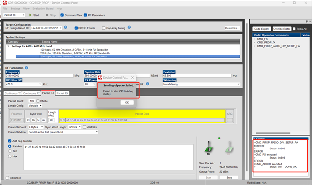
  • Thanks Ryan, the enable box can be checked now, however, when I open 20dbm in proprietary mode, it shows error. I then tested 5dbm without enable PA, it can run. Maybe more operations should be done in order to let it transmit in 20dbm?

  • maybe smartrf cannot let me do that,is there any method to use sysconfig or modify .c file directly to realize it?

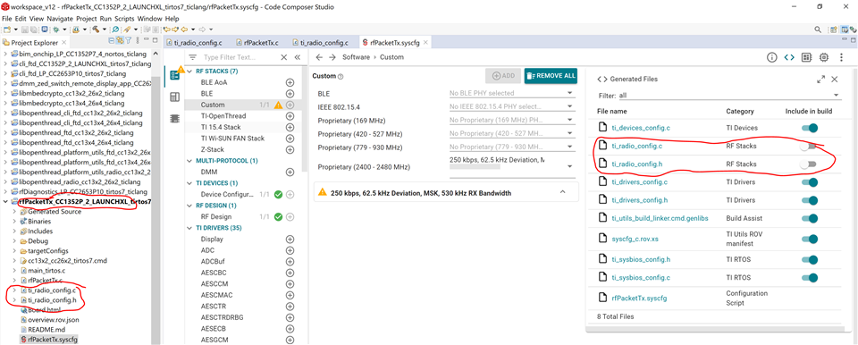
  • Can you please provide a screenshot of the error you are seeing?  Prop RF projects from the SimpleLink SDK also do not allow for High PA operation, thus you would need to generate custom ti_radio_config.c/h files (for RF overrides and power table settings) and ti_drivers_config.c/h files (for RF antennae switching) and exclude these files from being built in SysConfig.  You can sample from BLE or IEEE 802.15.4-based examples (including Zigbee, Thread, and 15.4-Stack) for references.  This issue is due to the fact that High PA operation has not been validated for Proprietary RF PHYs and thus are not supported by default.

    Regards,
    Ryan

  • Please refer to the error above when I change categories.xml. I think I should use CCS to build, could you please give me the detailed procedure so that I could use prop example: rfpacketrx and rfpackettx to update my 2652P firmware, and have them work in 20dbm? Thank you very much

  • I apologize as further research revealed that this is already a known condition.

    https://e2e.ti.com/f/1/t/805245 
    https://e2e.ti.com/f/1/t/1113840 
    https://e2e.ti.com/f/1/t/1169804 

    There are no detailed instructions for the feature you are requesting.  You can review the Prop RF User's Guide, especially the PHY ConfigurationTX Power and SysConfig sections, to get started with the custom build.

    Regards,
    Ryan

  • I was able to confirm high PA operation after making custom ti_radio_config.c/h files for +20 dBm on the 250 kbps MSK PHY, tested with the rfPacketTx example I found ~15 dBm increase in RSSI from a receiving device connected to Smart RF Studio 7.

    7585.ti_radio_config.c
    /*
     *  ======== ti_radio_config.c ========
     *  Configured RadioConfig module definitions
     *
     *  DO NOT EDIT - This file is generated for the CC1352P1F3RGZ
     *  by the SysConfig tool.
     *
     *  Radio Config module version : 1.17.2
     *  SmartRF Studio data version : 2.29.0
     */
    
    #include "ti_radio_config.h"
    #include DeviceFamily_constructPath(rf_patches/rf_patch_cpe_prop.h)
    
    
    // *********************************************************************************
    //   RF Frontend configuration
    // *********************************************************************************
    // RF design based on: LAUNCHXL-CC1352P-2
    
    // TX Power tables
    // The RF_TxPowerTable_DEFAULT_PA_ENTRY and RF_TxPowerTable_HIGH_PA_ENTRY macros are defined in RF.h.
    // The following arguments are required:
    // RF_TxPowerTable_DEFAULT_PA_ENTRY(bias, gain, boost, coefficient)
    // RF_TxPowerTable_HIGH_PA_ENTRY(bias, ibboost, boost, coefficient, ldoTrim)
    // See the Technical Reference Manual for further details about the "txPower" Command field.
    // The PA settings require the CCFG_FORCE_VDDR_HH = 0 unless stated otherwise.
    
    // 2400 MHz, 5 dBm
    RF_TxPowerTable_Entry txPowerTable_2400_pa5[TXPOWERTABLE_2400_PA5_SIZE] =
    {
        {-20, RF_TxPowerTable_DEFAULT_PA_ENTRY(6, 3, 0, 2) }, // 0x04C6
        {-18, RF_TxPowerTable_DEFAULT_PA_ENTRY(8, 3, 0, 3) }, // 0x06C8
        {-15, RF_TxPowerTable_DEFAULT_PA_ENTRY(10, 3, 0, 3) }, // 0x06CA
        {-12, RF_TxPowerTable_DEFAULT_PA_ENTRY(12, 3, 0, 5) }, // 0x0ACC
        {-10, RF_TxPowerTable_DEFAULT_PA_ENTRY(15, 3, 0, 5) }, // 0x0ACF
        {-9, RF_TxPowerTable_DEFAULT_PA_ENTRY(16, 3, 0, 5) }, // 0x0AD0
        {-6, RF_TxPowerTable_DEFAULT_PA_ENTRY(20, 3, 0, 8) }, // 0x10D4
        {-5, RF_TxPowerTable_DEFAULT_PA_ENTRY(22, 3, 0, 9) }, // 0x12D6
        {-3, RF_TxPowerTable_DEFAULT_PA_ENTRY(19, 2, 0, 12) }, // 0x1893
        {0, RF_TxPowerTable_DEFAULT_PA_ENTRY(19, 1, 0, 20) }, // 0x2853
        {1, RF_TxPowerTable_DEFAULT_PA_ENTRY(22, 1, 0, 20) }, // 0x2856
        {2, RF_TxPowerTable_DEFAULT_PA_ENTRY(25, 1, 0, 25) }, // 0x3259
        {3, RF_TxPowerTable_DEFAULT_PA_ENTRY(29, 1, 0, 28) }, // 0x385D
        {4, RF_TxPowerTable_DEFAULT_PA_ENTRY(35, 1, 0, 39) }, // 0x4E63
        {5, RF_TxPowerTable_DEFAULT_PA_ENTRY(23, 0, 0, 57) }, // 0x7217
        RF_TxPowerTable_TERMINATION_ENTRY
    };
    
    // 2400 MHz, 20 dBm
    RF_TxPowerTable_Entry txPowerTable_2400_pa20[TXPOWERTABLE_2400_PA20_SIZE] =
    {
        {14, RF_TxPowerTable_HIGH_PA_ENTRY(22, 3, 1, 19, 27) }, // 0x1B27D6
        {15, RF_TxPowerTable_HIGH_PA_ENTRY(26, 3, 1, 23, 27) }, // 0x1B2FDA
        {16, RF_TxPowerTable_HIGH_PA_ENTRY(30, 3, 1, 28, 27) }, // 0x1B39DE
        {17, RF_TxPowerTable_HIGH_PA_ENTRY(37, 3, 1, 39, 27) }, // 0x1B4FE5
        {18, RF_TxPowerTable_HIGH_PA_ENTRY(32, 3, 1, 35, 48) }, // 0x3047E0
        {19, RF_TxPowerTable_HIGH_PA_ENTRY(34, 3, 1, 48, 63) }, // 0x3F61E2
        {20, RF_TxPowerTable_HIGH_PA_ENTRY(53, 3, 1, 58, 63) }, // 0x3F75F5
        RF_TxPowerTable_TERMINATION_ENTRY
    };


    //*********************************************************************************
    //  RF Setting:   250 kbps, 62.5 kHz Deviation, MSK, 530 kHz RX Bandwidth
    //
    //  PHY:          2msk250kbps
    //  Setting file: setting_tc902.json
    //*********************************************************************************
    
    // PARAMETER SUMMARY
    // RX Address Mode: No address check
    // Frequency (MHz): 2440.0000
    // Deviation (kHz): 62.5
    // Packet Length Config: Variable
    // Max Packet Length: 255
    // Preamble Count: 4 Bytes
    // Preamble Mode: Send 0 as the first preamble bit
    // RX Filter BW (kHz): 529.8
    // Symbol Rate (kBaud): 250.000
    // Sync Word: 0x930B51DE
    // Sync Word Length: 32 Bits
    // TX Power (dBm): 5
    // Whitening: No whitening
    
    // TI-RTOS RF Mode Object
    RF_Mode RF_prop =
    {
        .rfMode = RF_MODE_PROPRIETARY_2_4,
        .cpePatchFxn = &rf_patch_cpe_prop,
        .mcePatchFxn = 0,
        .rfePatchFxn = 0
    };
    
    // Overrides for CMD_PROP_RADIO_DIV_SETUP_PA
    uint32_t pOverrides[] =
    {
        // override_tc902.json
        // DC/DC regulator: In Tx, use DCDCCTL5[3:0]=0x3 (DITHER_EN=0 and IPEAK=3).
        (uint32_t)0x00F388D3,
        // Rx: Set anti-aliasing filter bandwidth to 0x5 (in ADI0, set IFAMPCTL3[7:4]=0x5)
        ADI_HALFREG_OVERRIDE(0,61,0xF,0x5),
        // Tx: Configure PA ramp time, PACTL2.RC=0x1 (in ADI0, set PACTL2[4:3]=0x1)
        ADI_2HALFREG_OVERRIDE(0,16,0x8,0x8,17,0x1,0x0),
        // Rx: Set AGC reference level to 0x1E (default: 0x2E)
        HW_REG_OVERRIDE(0x609C,0x001E),
        // PDIFLINPREDEN = 0 (bit 3) PDIFLIMITRANGE = 1 (bit 0). Default 0x40F6 (0x40F7)
        HW_REG_OVERRIDE(0x50D4,0x40F7),
        // Enable piecewise linear shaper.
        (uint32_t)0x00810083,
        // Enable piecewise linear shaper.
        (uint32_t)0x001000A3,
        // No automatic shape programming.
        (uint32_t)0x000000C3,
        // No automatic shape programming.
        (uint32_t)0x000000E3,
        // 6 element override starting from 0x4040
        HW32_ARRAY_OVERRIDE(0x4040,6),
        // Shape override.
        (uint32_t)0x0000B19A,
        // Shape override.
        (uint32_t)0x00013199,
        // Shape override.
        (uint32_t)0x00000000,
        // Shape override.
        (uint32_t)0x00000000,
        // Shape override.
        (uint32_t)0x00000000,
        // Shape override.
        (uint32_t)0x00000000,
        (uint32_t)0xFFFFFFFF
    };
    
    // Overrides for CMD_RADIO_SETUP_PA
    uint32_t pOverrides_TxStd[] =
    {
        // override_txstd_placeholder.json
        // TX Standard power override
        TX_STD_POWER_OVERRIDE(0x7217),
        // The ANADIV radio parameter based on LO divider and front end settings
        (uint32_t)0x05320703,
        // override_txstd_settings.json
        // Set RTIM offset to default for standard PA
        (uint32_t)0x00008783,
        // Set synth mux to default value for standard PA
        (uint32_t)0x050206C3,
        // Set TXRX pin to 0 in RX and high impedance in idle/TX.
        HW_REG_OVERRIDE(0x60A8,0x0401),
        (uint32_t)0xFFFFFFFF
    };
    
    // Overrides for CMD_RADIO_SETUP_PA
    uint32_t pOverrides_Tx20[] =
    {
        // override_tx20_placeholder.json
        // TX HighPA power override
        TX20_POWER_OVERRIDE(0x003F75F5),
        // The ANADIV radio parameter based on LO divider and front end settings
        (uint32_t)0x01C20703,
        // override_tx20_settings.json
        // Set RTIM offset to 3 for high power PA
        (uint32_t)0x00038783,
        // Set synth mux for high power PA
        (uint32_t)0x010206C3,
        // Set TXRX pin to 0 in RX/TX and high impedance in idle.
        HW_REG_OVERRIDE(0x60A8,0x0001),
        (uint32_t)0xFFFFFFFF
    };
    
    
    // CMD_PROP_RADIO_DIV_SETUP_PA
    // Proprietary Mode Radio Setup Command for All Frequency Bands
    rfc_CMD_PROP_RADIO_DIV_SETUP_PA_t RF_cmdPropRadioDivSetup =
    {
        .commandNo = 0x3807,
        .status = 0x0000,
        .pNextOp = 0,
        .startTime = 0x00000000,
        .startTrigger.triggerType = 0x0,
        .startTrigger.bEnaCmd = 0x0,
        .startTrigger.triggerNo = 0x0,
        .startTrigger.pastTrig = 0x0,
        .condition.rule = 0x1,
        .condition.nSkip = 0x0,
        .modulation.modType = 0x0,
        .modulation.deviation = 0xFA,
        .modulation.deviationStepSz = 0x0,
        .symbolRate.preScale = 0xF,
        .symbolRate.rateWord = 0x28000,
        .symbolRate.decimMode = 0x0,
        .rxBw = 0x5B,
        .preamConf.nPreamBytes = 0x4,
        .preamConf.preamMode = 0x0,
        .formatConf.nSwBits = 0x20,
        .formatConf.bBitReversal = 0x1,
        .formatConf.bMsbFirst = 0x1,
        .formatConf.fecMode = 0x0,
        .formatConf.whitenMode = 0x0,
        .config.frontEndMode = 0x0,
        .config.biasMode = 0x1,
        .config.analogCfgMode = 0x0,
        .config.bNoFsPowerUp = 0x0,
        .config.bSynthNarrowBand = 0x0,
        .txPower = 0xFFFF,
        .pRegOverride = pOverrides,
        .centerFreq = 0x0988,
        .intFreq = 0x0800,
        .loDivider = 0x00,
        .pRegOverride = pOverrides,
        .pRegOverrideTxStd = pOverrides_TxStd,
        .pRegOverrideTx20 = pOverrides_Tx20
    };
    
    // CMD_FS
    // Frequency Synthesizer Programming Command
    rfc_CMD_FS_t RF_cmdFs =
    {
        .commandNo = 0x0803,
        .status = 0x0000,
        .pNextOp = 0,
        .startTime = 0x00000000,
        .startTrigger.triggerType = 0x0,
        .startTrigger.bEnaCmd = 0x0,
        .startTrigger.triggerNo = 0x0,
        .startTrigger.pastTrig = 0x0,
        .condition.rule = 0x1,
        .condition.nSkip = 0x0,
        .frequency = 0x0988,
        .fractFreq = 0x0000,
        .synthConf.bTxMode = 0x0,
        .synthConf.refFreq = 0x0,
        .__dummy0 = 0x00,
        .__dummy1 = 0x00,
        .__dummy2 = 0x00,
        .__dummy3 = 0x0000
    };
    
    // CMD_PROP_TX
    // Proprietary Mode Transmit Command
    rfc_CMD_PROP_TX_t RF_cmdPropTx =
    {
        .commandNo = 0x3801,
        .status = 0x0000,
        .pNextOp = 0,
        .startTime = 0x00000000,
        .startTrigger.triggerType = 0x0,
        .startTrigger.bEnaCmd = 0x0,
        .startTrigger.triggerNo = 0x0,
        .startTrigger.pastTrig = 0x0,
        .condition.rule = 0x1,
        .condition.nSkip = 0x0,
        .pktConf.bFsOff = 0x0,
        .pktConf.bUseCrc = 0x1,
        .pktConf.bVarLen = 0x1,
        .pktLen = 0x14,
        .syncWord = 0x930B51DE,
        .pPkt = 0
    };
    
    // CMD_PROP_RX
    // Proprietary Mode Receive Command
    rfc_CMD_PROP_RX_t RF_cmdPropRx =
    {
        .commandNo = 0x3802,
        .status = 0x0000,
        .pNextOp = 0,
        .startTime = 0x00000000,
        .startTrigger.triggerType = 0x0,
        .startTrigger.bEnaCmd = 0x0,
        .startTrigger.triggerNo = 0x0,
        .startTrigger.pastTrig = 0x0,
        .condition.rule = 0x1,
        .condition.nSkip = 0x0,
        .pktConf.bFsOff = 0x0,
        .pktConf.bRepeatOk = 0x0,
        .pktConf.bRepeatNok = 0x0,
        .pktConf.bUseCrc = 0x1,
        .pktConf.bVarLen = 0x1,
        .pktConf.bChkAddress = 0x0,
        .pktConf.endType = 0x0,
        .pktConf.filterOp = 0x0,
        .rxConf.bAutoFlushIgnored = 0x0,
        .rxConf.bAutoFlushCrcErr = 0x0,
        .rxConf.bIncludeHdr = 0x1,
        .rxConf.bIncludeCrc = 0x0,
        .rxConf.bAppendRssi = 0x0,
        .rxConf.bAppendTimestamp = 0x0,
        .rxConf.bAppendStatus = 0x1,
        .syncWord = 0x930B51DE,
        .maxPktLen = 0xFF,
        .address0 = 0xAA,
        .address1 = 0xBB,
        .endTrigger.triggerType = 0x1,
        .endTrigger.bEnaCmd = 0x0,
        .endTrigger.triggerNo = 0x0,
        .endTrigger.pastTrig = 0x0,
        .endTime = 0x00000000,
        .pQueue = 0,
        .pOutput = 0
    };


    7585.ti_radio_config.h

    Regards,
    Ryan

  • After modifying the program according to the discussion above and compiling it, I encountered the following error while debugging the program:

    Cortex_M4_0: Error: (Error -1170 @ 0x0) Unable to access the DAP. Reset the device, and retry the operation. If error persists, confirm configuration, power-cycle the board, and/or try more reliable JTAG settings (e.g. lower TCLK). (Emulation package 9.12.0.00150)
    Cortex_M4_0: Trouble Halting Target CPU: (Error -2064 @ 0x0) Unable to read device status. Reset the device, and retry the operation. If error persists, confirm configuration, power-cycle the board, and/or try more reliable JTAG settings (e.g. lower TCLK). (Emulation package 9.12.0.00150)
    .......
    Cortex_M4_0: Unable to determine target status after 20 attempts
    Cortex_M4_0: Failed to remove the debug state from the target before disconnecting. There may still be breakpoint op-codes embedded in program memory. It is recommended that you reset the emulator before you connect and reload your program before you continue debugging

    By debuging the code, I found that the above errors occur when executing the following command in 'rfPacketTx.c':

    /* Send packet /
    RF_EventMask terminationReason = RF_runCmd(rfHandle, (RF_Op)&RF_cmdPropTx, RF_PriorityNormal, NULL, 0);

    The execution of this data transmission command seems to be causing the above errors.

    After testing, it was observed that if the above transmission command is not executed, the program can run normally, and the data read from RF_getTxPower() confirms that it is +20dBm, indicating that the configuration is valid.

    Why is RF_cmdPropTx command not executed correctly here? It appears to hang when executing this command.
    Apart from the modifications mentioned above, are there any other modifications that need to be made?

    Thanks!

  • What is the Green LED behavior when running the application outside of the debugger?  I've highlighted all of the changes I applied to the example (SimpleLink SDK v7.10, CCS v12.3):


    Please note any differences between your own environment.

    Regards,
    Ryan

  • hi Ryan,

    thank you very much!it seems work well! Meanwhile, I would like to know how to use dsss in this 2.4g example so that I could get a better sensitivity? I read relevant document, and I add override command in povertide as “hw_reg_override(0x5068,0x030C) in Tx, but using Rx connected to smartrf to test lowest rssi using ATTENUATOR, it appears to remain -95dbm sensitivity, far from the datasheet data when dsss=4 or 8. Could you tell me where goes wrong?

  • What relevant document are you referring to?  TI cannot provide much assistance if you are choosing to override the radio registers outside of the verified PHYs and tools provided.

    Regards,
    Ryan

  • Hi Ryan, I'm referring to swra636c.pdf, which specified the ability to activate DSSS in CC1352 prop mode, since CC1352 has same design as CC2652, I suppose CC2652P should have the same ability in 2.4GHz prop mode.

    Thanks!

  • I do not see where this is explained in SWRA636, however you should avoid assuming that overrides applied to a Sub-1 GHz PHY are equivalent for a 2.4 GHz PHY.

    Regards,
    Ryan