This thread has been locked.

If you have a related question, please click the "Ask a related question" button in the top right corner. The newly created question will be automatically linked to this question.

LP8556: Overvoltage protection

Guru 29720 points
Part Number: LP8556


Hi Team,

I would like to ask the following questions about LP8556.

1)
The datasheet shows VOVP is "VBOOST + 1.6V" (typ).


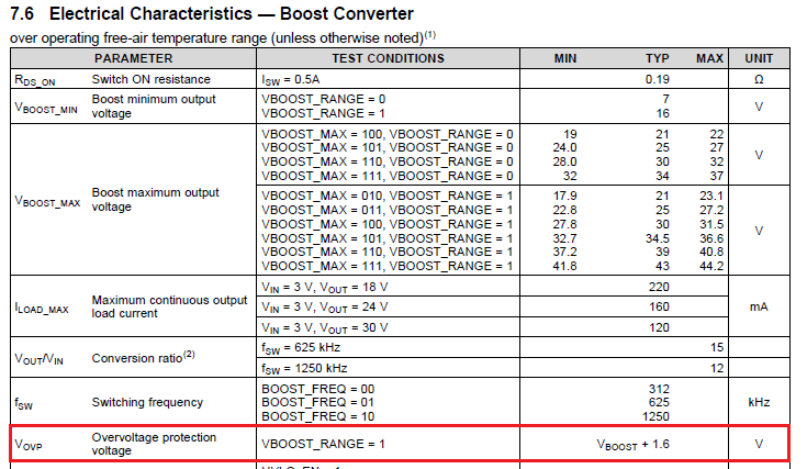
I believe this "VBOOST" indicates typical value of VBOOST_MAX.
Is my understanding correct?

2)
Is there typical value of VOVP under VBOOST_RANGE = 0?

3)
I believe internal FET is turned off rest of the cycle when LP8556 detects OVP, and LP8556 restarts switching if VBOOST decreases under OVP threshold by next cycle.
Is my understanding correct?
I would like to know if there is hysteresis or not.

Best Regards,
Yaita / Japan disty

  • Hi Yaita,

    1. For Vovp, the VBOOST in VBOOST + 1.6 does not refer to VBOOST_MAX, it refers to a "target" VBOOST with current loading condition.

    2. Let me find out more and get back to you on this.

    3. For LP8556, nothing gets turn off. In the event of OVP, the fault register is updated, and that is about it.

    Regards
    H L

  • Hi Hak-Leong,

    I would like to clarify the followings.

    >1. For Vovp, the VBOOST in VBOOST + 1.6 does not refer to VBOOST_MAX, it refers to a "target" VBOOST with current loading condition.
    Does it refer to the VBOOST voltage that is calculated by the following equation (1)?
    I would like to know if it is applicable in case of "adaptive boost voltage control".
    (datasheet page 14)
    VBOOST = VBOOST_MIN + 0.42 × VBOOST[dec]  (1)


    >3. For LP8556, nothing gets turn off. In the event of OVP, the fault register is updated, and that is about it.
    It seems the following block diagram in page 13 shows OVP stops switching. Is it typo?


    Best Regards,
    Yaita

  • Hi Yaita,

    OVP detection is based on Vboost + 1.6V, and it applies to both VBOOST_RANGE = 0 and VBOOST_RANGE = 1.  For LP8556 in adaptive mode, Vboost is not a fixed value, it depends on the load (Vf of LED), if there is a gradual change in Vf (from cold to hot), the trip point for OVP moves as well. In this case, OVP is more for detecting a sudden change in Vboost.

    You are right on OVP stops the boost switching, but it does not stops the driver. If there is a spike in vboost for a short time, the switch stops, but the driver continues to draw current from boost . Once the vboost level returns to normal, the driver continues to operate.

    Regards
    H L

  • Hi Hak-Leong,

    Thank you for your support.

    The following waveform is VBOOST pin voltage my customer got under low LED brightness(light load).
    It seems VBOOST voltage is stable (no sudden change in VBOOST voltage) however OVP flag (bit3 of 02h status register) shows "1" at all times.
    He read 02h register many times but OVP flag wasn't cleared in this case.


    Is it possible case for LP8556?
    I couldn't catch why OVP flag shows "1" all the times in this case so your any advice is appreciated.

    Best Regards,
    Yaita / Japan disty

  • Hi Yaita,

    Is customer operates in direct PWM mode? if not, can you provide more details on the condition such that LP8556 exhibits this behavior? I can try to duplicate this on our EVM if you can provide the value of Vin, number of LEDs used, Vf of the LED etc.

    Regards
    H L
  • Hi Hak-Leong,

    Thank you for your kind support.

    >Is customer operates in direct PWM mode?
    No, it is adaptive control mode.
    I think it is difficult to duplicate this because it occures only one specific board in so many board they have.
    I am wondering about this issue because VBOOST voltage is stable, so it is helpful if you have any comments how to research this issue.

    Best Regards,
    Yaita

  • Hi Yaita,

    If this is one out of many, is this the same IC with high VBOOST pin leakage? If this is the only one IC that is having all these issues, I suggest you contact the FAE and send the device to TI as a return unitso we can examine it in more detail.

    This forum is more suitable for general issues; I suggest lets go through FAE and connect via email on this particular unit.

    Regards
    H L
  • Hi Hak-Leong,

    Thank you for your continuous support. I understood.

    Please allow me to ask one more.
    What voltage is "normal" voltage that you commented below?
    --------------------------------------------------------
    You are right on OVP stops the boost switching, but it does not stops the driver. If there is a spike in vboost for a short time, the switch stops, but the driver continues to draw current from boost . Once the vboost level returns to normal, the driver continues to operate.
    --------------------------------------------------------
    I believe VBOOST is adaptively adjusted in Adaptive Boost Control mode so I couldn't catch what is the normal voltage.

    Best Regards,
    Yaita

  • Hi Yaita,
    I think the "normal" in your quote means the target boost output voltage decided by control loop, which is decided by Headroom voltage and control loop calulation.
  • Hi Caryss-san,

    Thank you for your kind support.
    I understood OVP circuit monitors the voltage on VBOOST pin to detect OVP.
    Which does LP8556 monitor the voltage on VBOOST pin or LEDx pin to recover from OVP?

    Best Regards,
    Yaita

  • Hi Yaita-san,
    To recover form OVP, both Vboost and LEDx pins are monitored. The LEDx pins voltage is the input to calculate the "normal" boost voltage and Vboost pin is sensing real output voltage.
  • one update here, "OVP detection is based on Vboost + 1.6V " is applied to VBOOST_RANGE = 1. as for VBOOST_RANGE = 0, the detection range is smaller.
  • This issue has been solved through email. I will close this thread.