Part Number: DRV8837
Tool/software:
HI,
Are there any H bridge ICs from TI which will support capacitive loads.
Best Regards,
Shafeeq
Part Number: DRV8837
Tool/software:

Hi we are having some inrush current issues with the motor drivers that were resolved with series resistors at the output.
However, we are diagnosing some potential issues that are resolved by power cycling the input power. We are not sure if it may be from using the drivers in this way. This schematic includes two pairs of drivers, where each of the pairs have the input logic and power as well as the outputs in parallel.
Is it possible for this to cause backfeeding and if so is there a way you would recommend resolving the issue?
Thanks,
Nikh
Part Number: DRV8837
Tool/software:
Hi,
I have a lens module in which the lens' aperture is controlled via a DC-Iris motor (2 Iris Blades mechanism galvanometer drive). I wish to control the lens to fully open, partially open i.e. (25%,50%,75%) and fully close. Could you please recommend a suitable motor driver that can accomplish these functions?
My DC-Iris has 4 wires: 1. Driving+ 2. Driving - 3.Stopping+ 4. Stopping-. I have a Panasonic AN41908A demo-kit that can perform above function through the Iris Drive internal module but I want to explore other alternative parts because there is lack of documentation from Panasonic explaining how to configure the IC to properly drive the driving and stopping coil of DC-Iris. I looking at the datasheet of TI DRV8837 but there is only two wires available to connect to the motor (my DC-Iris has 4 wires)
Thank you
Part Number: DRV8837
Tool/software:
Hello,
I'm currently using a DRV8837 in my design.
I evaluated a DRV8213EVM for its current regulation capabilities and really liked what the GUI was able to do with the PWM ramp up.
Therefore, I am attempting to duplicate the PWM ramp up in the DRV8213EVM with the DRV8837 chip by monitoring the DRV8213EVM's IN1 and IN2 signals.
First question - the frequency selected on the GUI (50kHz) does not represent the frequency of what is monitored (25-50Hz) on IN1 and IN2 for the DRV8213EVM.
Secondly, even when I have the DRV8837's IN1 and IN2 identical to the DRV8213EVM, and turning off the current monitoring and regulation features of the DRV8213EVM - I am noticing that the DRV8213EVM's start up current is much lower than the DRV8837's (with the same load, VM bulk capacitors, etc). Is there something fundamentally different about the DRV8213 that is not in the DRV8837 that allows it to have a better PWM ramp?
Part Number: DRV8837
Tool/software:
Hello,
I am working on a project using the DRV8837 motor driver. We have a regulated voltage supply (Vm) of 10.5V. During braking, we have observed that the OUT1 and OUT2 pins can experience voltage spikes between 12V and 13V for approximately 20µs.
We would like to know if these voltage spikes pose a risk of stress or damage to the DRV8837. Specifically, we are concerned about the maximum voltage tolerance of the OUT1 and OUT2 pins.
Could you please provide information on:
Thank you for your assistance.
Sincerely,
Nicolas
Part Number: DRV8837
Tool/software:
At present, there is a problem that the output will have a short time jump in the process of using DRV8837 two high and low jumps at the same time. How does this problem occur and how should it be solved?

Part Number: DRV8837
Dear ,
Only several pieces of DRV8837 can not work in low temperature ?
is it quality problem ? Exchange with good DRV8837, bad board become good board, good board become bad board.
if it is quality problem, how to handle it ?
Part Number: DRV8837
Tool/software:
Hi.
I am modifying the zoom lens control circuit.
Previously, the zoom, focus, and iris were all "Motrized", so I used DRV8837DSGT to control them.
The iris of the zoom lens has been changed to "DC Auto Iris".
1. Can I use DRV8837 as the iris control circuit?
2. If modification is needed, can you recommend a DC Auto Iris driver?
3. Can you provide a sample schematic?
4. The zoom lens information is as follows:

Regards
Part Number: DRV8837
Tool/software:
Hi,
I designed a board to control a small dc motor using DRV8837CDSGR and nRF52832 MCU.
Here is the schematic design
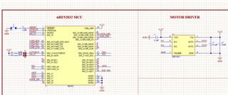
Somehow, the moto driver isn't working at all.
I am sending a simple toggle code to drive motor but motor is not running. I tested the motor with external supply. It worked fine.
Can someone help me with it plz?
#include <stdbool.h>
#include <stdint.h>
#include "nrf_delay.h"
#include "nrf_gpio.h"

/**
 * @brief Function for application main entry.
 */
 #define IN1 10
 #define IN2 9
 #define nslp 11
int main(void)
{
    nrf_gpio_cfg_output(IN1);
    nrf_gpio_cfg_output(IN2);
    nrf_gpio_cfg_output(nslp);


    /* Toggle LEDs. */
    while (true)
    {
     nrf_gpio_pin_set(nslp);
     nrf_gpio_pin_clear(IN2);
     nrf_gpio_pin_set(IN1);
     nrf_delay_ms(3000);
     nrf_gpio_pin_clear(nslp);
     nrf_gpio_pin_clear(IN1);
     nrf_gpio_pin_set(IN2);
     nrf_delay_ms(3000);

    }
}
Part Number: DRV8837
given that the DRV8837 doesn't have internal clamping diodes, for a motor or solenoid application, these will need to be added externally, correct? If so, do you have a similar device that has the clamping diodes integrated or will the DRV8837 with external diodes be a smaller solution?
Thanks!