Part Number: TLVM13660EVM
I am using the TLVM13660 EVM with the jumpers set for a 5.0V output and 800KHz switching frequency. I am getting good output voltage and efficiency with low ripple, but the ripple frequency seems to be defaulting to about 250KHz or so. I have tried the other FSW settings and still the ripple freq is only about 250KHz. I confirmed the resistor for the 800KHz jumper setting is 16.5KOhm. Please advise.
Part Number: TLVM13630EVM
Tool/software:
I purchased two TLVM13630EVM units for evaluation. Following the user's guide, I selected 5.0v, 1.0MHz, and selected enable ON (J5). I connected a 22v battery to VIN with a switch. As soon as I turned it on, there was a loud pop and there is no output voltage at VOUT. I tried the same thing again on the second board and the same thing. Now I have two dead boards.
What did I do wrong?
Hi Ryusuke,
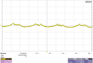
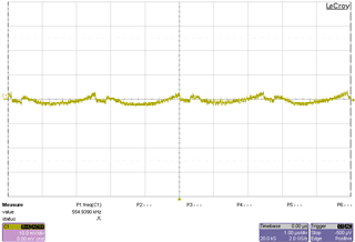
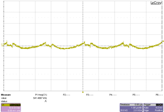
Here are some of the output voltage ripple waveforms that I found near your use case. I used the TLVM13660EVM.
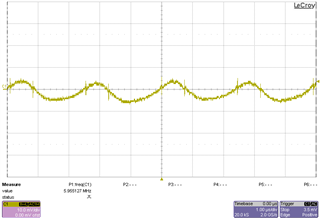
12 VIN 3.3 VOUT 4 A 500 kHz ~ 10 mV pk-pk

12 VIN 3.3 VOUT 6 A 500 kHz ~ 9 mV pk-pk
12 VIN 1.8 VOUT 4 A 500 kHz ~ 5 mV pk-pk

12 VIN 1.8 VOUT 6 A 500 kHz ~ 8 mV pk-pk
12 VIN 1.2 VOUT 4 A 500 kHz ~ 4 mV pk-pk
12 VIN 1.2 VOUT 6 A 500 kHz ~ 8 mV pk-pk\
Hope this helps,
Joshua Austria
Hello,
The calculator tool is an excel spreadsheet that will help with designing the components to meet the datasheet recommendations.
CBOOT should be set based on the recommended value in the datasheet. RBOOT is the resistor that can be tuned to slow down the SW rising slew rate which will help reduce the SW node ringing on the rising fast edge and improve EMI. The calculator tool does not have any simulation on this behavior.
I have contacted the web content manager to get more insight on why the download button for this calculator tool is missing.
However this calculator tool would not provide much insight on RBOOT resistor tuning. As such I suggest taking the TLVM13660EVM, tune the RBOOT resistor to your satisfaction, and measure the SW node.
Regards,
Jimmy