This thread has been locked.

If you have a related question, please click the "Ask a related question" button in the top right corner. The newly created question will be automatically linked to this question.

LM358: Low Pass Filter Design

Part Number: LM358
Other Parts Discussed in Thread: ADS1115

Hi,


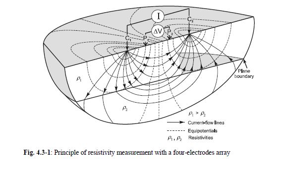
I am developing a geophysical measuring device to measure soil resistivity. and we measure the voltage values ​​from the ground. these are in the millivolt order. We encountered a problem like this: the electricity grid of the city is 50 Hz and the voltage at this frequency affects our measurements. 50 hz is a source of noise for us and we have to eliminate this noise. For this, I am designing a low pass filter using the lm358 op-amp.

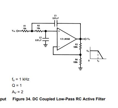
 My question is for 50 hz cutoff frequency, what is resistor and capacitor value? i know the general formula of the cutoff frequency that is fcutoff=1/(2*pi*R*C). but which resistor value for capacitor value is true? we can obtain to 50 hz for cuttoff with using different resistor and capacitor. i guess this must be little bit different for example i can use uF capacitor with big resistor value or i can use pF capacitor with smaller resistor value. and again we can obtain same 50 hz cutoff frequency. which of them will be good for my circuit? 


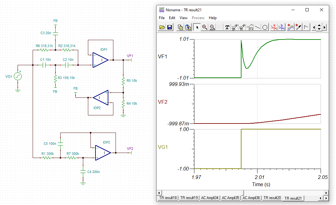
Below is a sample drawing of the filter I am trying to design

  • For this circuit, the gain is 1 + (R3 / R4), and the corner frequency is 1 / (2 π √(R1 R2 C1 C2)).

    This is a second-order low-pass filter, with a roll-off of 40 dB per decade. How much do you want to reduce the 50 Hz noise? I guess your measurement is DC?

    How much can you load the sensor? What is its output impedance? What is the voltage range? How much error can you afford?

  • Hi Metin,

    to avoid polarisation and passivation effects, an AC measuring method is usually chosen for soil resistivity measurements. This will also help to overcome the bad influence of the forming of electro-chemical potentials during the measurement:-)

    Kai

  • Well Metin, aside from basic filtering are you really expecting a 1kHz cutoff to filter a 50Hz ingress? 

  • Clemens Ladisch said:

    For this circuit, the gain is 1 + (R3 / R4), and the corner frequency is 1 / (2 π √(R1 R2 C1 C2)).

    This is a second-order low-pass filter, with a roll-off of 40 dB per decade. How much do you want to reduce the 50 Hz noise? I guess your measurement is DC?

    How much can you load the sensor? What is its output impedance? What is the voltage range? How much error can you afford?

    The basic setup for a resistivity survey involves using a resistivity meter and four electrodes.

    The resistivity meter is a device that acts as both a voltmeter (measuring V) and an ammeter (measuring I) and records resistance values (V/I).

    I use 0.5 hz square wave to give electric to soil. A, B point current points and M, N points potantial points. the current gives to soil with using AB points.
    With the effect of the current given to the ground from ab points, a potential field occurs between the mn points.

    I want to measure potential field. but the potantial field has a noise. and we try to clean noise of potantial field. I use ads1115 to measuring to potential field. measuring range +4 v to -4 volt. but the actual measured potential is  millivolts , it's between +1 and -1 volts.

  • Michael Steffes said:

    Well Metin, aside from basic filtering are you really expecting a 1kHz cutoff to filter a 50Hz ingress? 

    of course not. I want to change rc values to obtain 50 hz cutoff frequency. this is a low pass filter example circuit for lm358. i think we can modify it for 50 hz.

  • kai klaas69 said:

    Hi Metin,

    to avoid polarisation and passivation effects, an AC measuring method is usually chosen for soil resistivity measurements. This will also help to overcome the bad influence of the forming of electro-chemical potentials during the measurement:-)

    Kai


    Thanks for the tip, Kai. but I mean different things that measure soil resistance. I explained what I was talking about in the message above.

  • Hello Metin,

    You are correct, the driving equation of your LPF will be f(-3dB) = 1/(2*pi*R*C)

    The main design question you will be having is if you are trying to filter 50Hz noise, how large of a capacitor can you introduce before introducing stability issues, then once you have that value, you can size your resistor appropriately.

    You should be able to run stability analysis on your circuit in either PSpice for TI or TINA-TI without too much difficulty (and with a little help from the precision labs video series). It's also worth noting there are other techniques to be able to get away with a larger capacitor. You should also be aware of the errors that each method introduces, and evaluate whether those errors are acceptable in your design.

    Best,
    Jerry

  • Thank you Jerry. your suggest is very useful for my problem.

  • Hi Metin,

    so you are applying the Van der Pauw method?

    Have you thought about using a 50Hz notch filter?

    Is 50Hz the only frequency disturbing your measurement?

    Kai

  • kai klaas69 said:

    Hi Metin,

    so you are applying the Van der Pauw method?

    Hello Kai,
    I use direct current resistivity method to solve geophysical problems. Van der Pauw method is different thing. Direct current (dc) resistivity methods use artificial sources of current to produce an electrical potential field in the ground. In almost all resistivity methods, a current is introduced into the ground through point electrodes (C1, C2) and the potential field is measured using two other electrodes (the potential electrodes P1 and P2), as shown in Fig. 4.3-1. The source current can be direct current or low-frequency (0.1 - 30 Hz) alternating current. The aim of generating and measuring the electrical potential field is to determine the spatial resistivity distribution (or its reciprocal - conductivity) in the ground. As the potential between P1 and P2, the current introduced through C1 and C2, and the electrode configuration are known, the resistivity of the ground can be determined; this is referred to as the “apparent resistivity”

    kai klaas69 said:

    Have you thought about using a 50Hz notch filter?

    Is 50Hz the only frequency disturbing your measurement?

    Kai

    main problem of our measurements, power lines. they are everywhere and has 50 hz frequency. it has an effect disturb our waveform. notch filter which has 50 hz cutoff frequency may be useful to filter noise. Can you help anbout this?

  • Hey Metin, 

    This article should prove useful in your design: .

    All the best,
    Carolina

  • Thank you Carolina. Yes it's very useful. 

  • Hi Metin.

    here comes a simulation file for you to play with :-)

    metin_notch.TSC

    Kai


  • Kai, thank you very much. I'm just starting to try it, you saved my life :-)

    By the way, the op-amps what used in the circuit  is  lm358 op-amps?

  • Hi Metin,

    the OPAmp I used is an ideal OPAmp. This in order to show the pure performance of these filters topologies without being affected by the nonideal behaviour of a certain OPAmp model.

    The components with an asterisk run through two values in the simulation, asuming +1% tolerance and -1% tolerance. This helps to find out how the curve is looking with worst case manufacturing tolerances of components. (The resistors are assumed to have manufacturing tolerances of +/-0.1%.)

    Feel free to rise your questions, if you have some :-)

    Kai