This thread has been locked.

If you have a related question, please click the "Ask a related question" button in the top right corner. The newly created question will be automatically linked to this question.

ultrasonic directional speaker driver

Other Parts Discussed in Thread: TAS5634, TPA3255, DRV5825P

Hi!

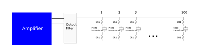
I want to make a ultra directional speaker. This is comprised by an array of small ultrasonic transducers of this kind; https://www.murata.com/en-us/products/productdetail?partno=MA40S4S.

The idea is to use a carrier of the frequency of the transducer (40kHz in this case), modulated in amplitude with the audio signal, and send it to the power amplifier.

The question is what IC would be a good amplifier for, let's say, 100 pcs of these in parallel? Could I use a 'normal' Class D amplifier, like this one: www.ti.com/.../TAS5825P (I would replace the output inductors for resistors in this case)? or should I go for something like this one: https://www.ti.com/product/DRV5825P

or there is something completely different out there which is much better option?

Thanks in advance.

  • Hi Jano,

    Can you please clarify what you mean by 100 pcs of these in parallel? Do you mean 100 separate channels or 100pcs all running in parallel into one load? 

    The more details you share about your system the better. What PVDD voltage? Expected load? Current requirements to that load? 

    Thank you,

    Robert Clifton 

  • I mean 100 pcs in parallel in one load. For the voltage, the example transducer linked in my previous message can handle 20Vpp, but there are some others which can handle up to 60V, then something in the range of 20-60V if possible. The current will be a bit more difficult to know beforehand, I will probably need to add some resistors in series to filter the output, but maybe 2-3A. If there is nothing possible in that current range I can think on splitting the load.

    But for me the most difficult part to know is if a part will be able to handle the frequency range, amplifiers are normally specified for audio ranges and that ends in 20kHz max. 

    Also the two amplifiers I linked as examples, have digital inputs, maybe an analog input can make it easier (at least on a first stage). 

  • Hi Jano,

    I wouldn't recommend getting a 100pcs in parallel. We can't guarantee that they will all switch at the exact same time and that the FETs will equally share the current evenly between them. I'd recommend using a single device to drive the transducers. 

    Needing an output voltage of 60Vpp would be challenging to do. The only device that might be able to do it in the audio amplifier portfolio would be the TAS5634. I'm not sure what the internal bandwidth is of that device so I'd have to investigate that. You would still need to have inductors on the outputs to ensure that the device can protect itself in an overcurrent event though. 

    If you are needing only 20Vpp you would have a lot more options. I'm not sure if you have the flexibility to choose only 20Vpp ultrasound transducers. 

    Let me know your thoughts.

    Best Regards,

    Robert Clifton 

  • Hi Robert

    I think we are talking about different ideas here, maybe I didn't explain myself right, perhaps with a diagram is easier:

    the 0R1 resistors I'm adding here, is an idea on how to control the differences among the transducers. The load will be mostly capacitive, but the capacitance should not be so high (the transducer on the example has 2.5nF, then all of them together 250nF).

     I'm not sure what the internal bandwidth is of that device so I'd have to investigate that.

    is there a way to tell the bandwidth of any of this kind of amplifiers out of the datasheet?

    for the output voltage, I would like to keep open possibilities in both places, the transducers and the amplifier. Then 20Vpp in bridge configuration could be also an option to consider. Can you suggest some part numbers?

  • Hi Jano,

    Oh you meant 100 transducers not 100 amplifiers! This makes a lot more sense! 

    Some of our devices mention their bandwidths in the datasheet. For example, the TPA3255 datasheet mentions the bandwidth is 100kHz. 

    If the bandwidth isn't mentioned in the datasheet then it would have to be investigated further by our design team. I would rather limit the list of potential devices to ask about before making the request to them! 

    Since you are driving a capacitance load I think the DRV5825P might be a good fit. It was specifically designed to drive capacitive loads! 

    Best Regards,

    Robert Clifton

  • Great! I will try this two options.

    Also the TPA3255 is popular, there are many inexpensive amplifiers on the market based on it, I may just need to change the output filter, and it's easy to test since the input is analog.

    For the DRV5825P I need to set the bandwidth at the highest, right?

    Thanks a lot!

  • Hi Jano,

    I would follow the datasheets suggestions but if you want to experiment with different bandwidths you are certainly free to do so!

    Best Regards, 

    Robert Clifton