This thread has been locked.

If you have a related question, please click the "Ask a related question" button in the top right corner. The newly created question will be automatically linked to this question.

INA212: Use INA212 as current sense amplifier to measure 1.4uA current

Part Number: INA212
Other Parts Discussed in Thread: LMC6001, INA190

Hi Team,

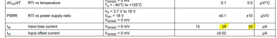
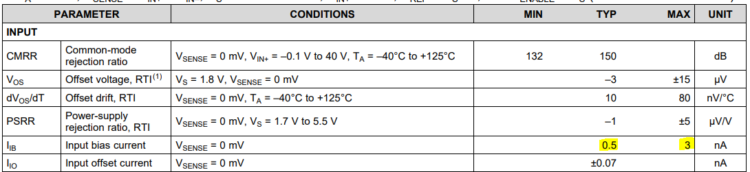
Our customer would like to use INA212 op-amp as a current sense amplifier to measure 1.4uA current with the use of 1 ohm sense resistor. Please see the schematic diagram below. Is the INA212 suitable for this application? If not, can we use LMC6001 instead? Can you please suggest a better alternative? 

INA212 block diagram for TI tech support.pdf

Regards,

Danilo 

  • Danilo,

    Without diving into the schematic too much, I can say with confidence that the INA212 will not work for this application. The input bias currents of this device are far too large to measure the desired 1.4uA with any certainty here. The bias currents flow into the inputs of the device, and the IN- side current will flow across the shunt along with the desired current. The amplitude of this current is >30x the current the customer is trying to measure here, making the measurement effectively useless. The offset voltage would also cause additional issues here. 

    From the current sensing amplifier portfolio, the best device suited for this level of measurement is the INA190, which reduces the bias current to nanoamps, making microamps an achievable target, but care must be taken with the design. For example, I would recommend they choose a shunt much larger than 1Ω to ensure that the sense voltage generated is ratiometrically much larger than the offset of the device:

    As shown here, the worst case offset of the INA190 can be 15uV, so the proposed 1.4uV sense voltage they are proposing is 10x smaller than this voltage. They need to generate a sense voltage proportionally larger than this offset to reduce the error to an acceptable value. Let me know if you have questions on this. 

    Examining the customer schematic, are they planning to use this to monitor a negative rail? This will also have implications for device selection, as the device will need to be able to handle a negative common mode voltage, and this will further limit options.