This thread has been locked.

If you have a related question, please click the "Ask a related question" button in the top right corner. The newly created question will be automatically linked to this question.

LMH6321: LMH6321:How to use Vcl pin for simple current limit ?

Part Number: LMH6321
Other Parts Discussed in Thread: TL431, BUF634

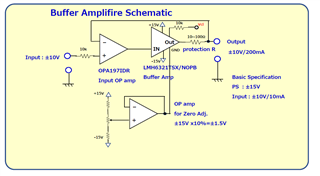
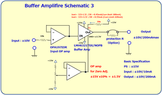
Hi, I'm planing to use LMH6321 and would like to use utilizing Vcl pin with setup of 200mA current limit.

But unfortunately I'm not sure how to use Vcl current limit correctly,

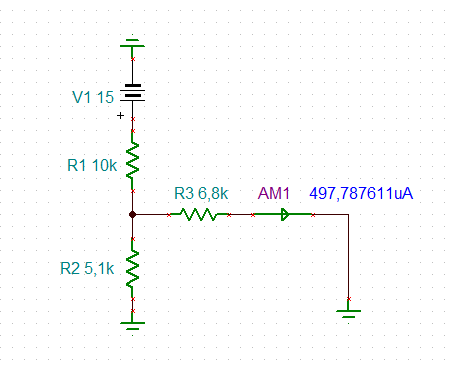
In the datasheet Rext should be 10kΩ、And Iext = Vprg/Rext.

And current limit value Isc= 2x200(Iext)=400Iext.

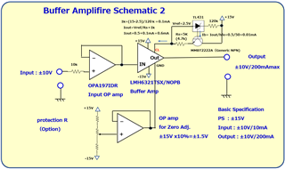
In my case, Isc = 200mA , then Iext should be 0.5mA (It mean Vprog = 5V+Vertual GND is needed,right?)

So I have to prepare power source for Vprog using small LDO or voltage reference like TL431, right?

I would like to make Vertual GND with OP amp and voltage divider (and pod), then this solution seems

very complicated as a current limit circuit.

Could you tell me more simple solution for this problem if you could?

Best regards,

  • What supply voltages do you want to use?

    A schematic would be helpful Relaxed

    Kai

  • Hi,

    Kai is correct to ask about your supplies, because the mid-supply virtual ground is only necessary if you are trying to operate on a single supply. If you are in dual supply mode, you can simply ground the GND pin and drive the CL pin with the correct voltage based on Rext. You must be careful in choosing Rext, as you should not violate the maximum CL to GND voltage of +/- 1.2V

    Best,
    Sam

  • Hi, Kai-san, Sam-san

    Thank you very much for your quick reply.

    I would like to attach the schematic.

    At first , I was using buf634 with protecting Register 10-100Ω.

    After that I found LMH6321 as a improved alternative buffer IC.

    Then I'm wondering how to change circuit for current protection using Vcl instead of protection Register.

    Your assistance is highly appreciated.

    Best regards,

  • Hi, all.

    Thank you very much for your support.

    I'd like to attach improved version of the Buffer Amplifire w/current limit Schematic.

    This time I added a TL431 shunt regulator circuit.

    Could you kindly give me advice for this solution ?

    The trouble is that regarding Iout.

    In this schematic, Iout to CL pin should be 0.5mA for 200mA current limit but irrelevant effect of Ik, 0.1mA or so is added.

    I'm wondering how to reject this Ik current effect.

    Your assistance is highly appreciated.

    Best regards,

  • You could do it this way, or similar:

    Kai

  • Hi, Kai-san.

    Thank you for your kind reply.

    I prefer your solution,it is simpler than mine no complicated.

    But I'm wondering because GND level will change ±2V by zero adjust circuit.

    It mean GND level varies 17V to 13V.

    Therefore regarding your circuit, current limit will vary 13% or more, right?

    But it may not matter if the current limit varies from 170mA to 230mA.

    Cause I am planing to use 0 to 100mA, so the current limiter is just for protection.

    Anyway, thank you for your support.

    And one thing forgotten, could you tell me about AM1 on your schematic?

    It seems that one way current so diode for prevent reverse current is not needed, right?

    I would like to close this issue.

    Best regards,

  • Why would you want to change the GND potential?

    There's no diode Relaxed. The tiny green triangle is part of the symbol of current meter AM1. It indicates the direction of current flow.

    Kai

  • Hi Kai-san,

    Thank you again  for your kind reply.

    > Why would you want to change the GND potential?

     As I mentioned in schematic, we need zero adjust ±1.5V with operational amp.

    Therefore, I thought it may be need 0.5mA constant current source or so.

    But current limit 180mA to 220mA tolerance seems to be no problem as your advice.

    I have changed schematic attached below.

    How about that schematic?

    It still have to branch current from +15V and 10k with 5.1k and 6.8k ?

    Your assistance is highly appreciated.

    Best regards,

  • I don't think that the GND pin of LMH6321 is for offset voltage adjust. It's only a reference voltage for the internal current limit control circuit shown in figure 53.

    The advantage of my "three resistor voltage divider" is, that the control pin sees a 10k resistance: ((10k // 5k1) / 6k8) = 10k18. For the case that this plays a role Relaxed

    Kai

  • Hi Kai-san,

    Thank you again and again for your kind reply!

    I somehow misunderstood the meaning of LMH6321 GND pin in the datasheet.

    Obviously only on the figure53 shows GND pin function.

    The Basic LMH6321 function is on the figure 51, there is no GND almost same as old BUF634.

    >I don't think that the GND pin of LMH6321 is for offset voltage adjust. It's only >a reference voltage for the internal current limit control circuit shown in figure 53.

    Therefore I would like to connect GND pin to GND, and to add offset control function to change 1st Input OP amp circuit.

    >The advantage of my "three resistor voltage divider" is, that the control pin >sees a 10k resistance: ((10k // 5k1) / 6k8) = 10k18. For the case that this plays a role

    =
    => I understood now.
     Because CL pin impedance from source should be 10kΩ fixed, that is why you advised me to use "three resistor voltage divider".

    It was very good for me to ask this issue on this forum.

    Again, thank you very much.

    Best regards,