This thread has been locked.

If you have a related question, please click the "Ask a related question" button in the top right corner. The newly created question will be automatically linked to this question.

INA1620: INA1620

Part Number: INA1620
Other Parts Discussed in Thread: OPA1642, OPA1622

Dear TI Support Team,

I would like to clarify some points with INA1620 when using it as Headphone Amplifier.

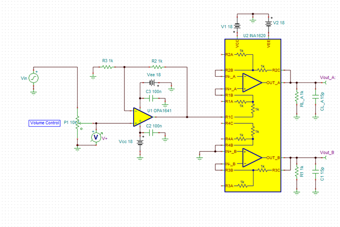
1. According to schematic attached, the Active LPF analog output is first connects to 10K volume pot and then goes to INA1620 noninverting inputs. INA1620 is configured in a unity gain.

My question are:

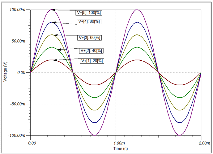
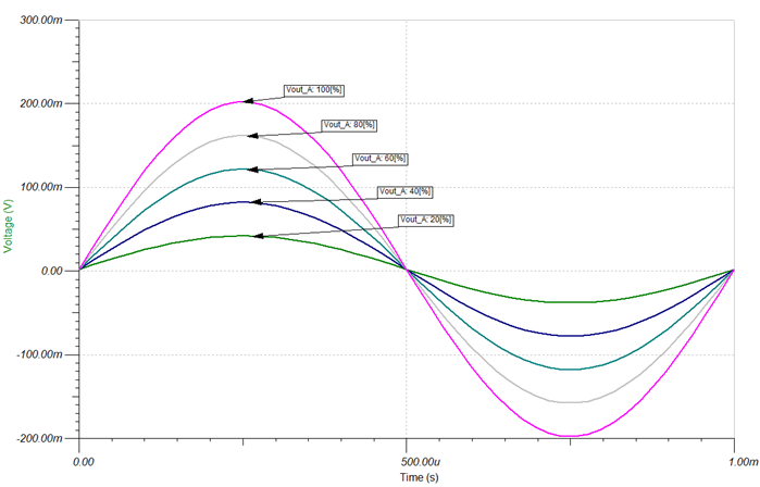
1.Does the performance and sound quality of INA1620 effected, taking into account that the pot has variable resistance and INA1620 has its own internal 1K resistor and the combined resistance always varies.

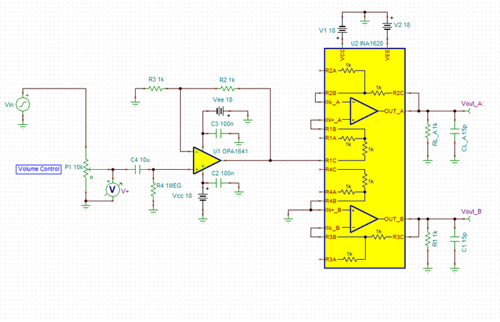
2. In some forum threads I read that it's recomended to place an OPAMP as a buffer before the INA1620, is it correct to do so?

3. If placing an OPAMS is correct, then could you please recomend or help me alter the schematic attached including the components nominals, so that it lets me use the INA1620 to its full potential.

Thanks and best regards,

  • Hello,

    I have simulated the circuit in TINA Ti and attached the simulation for your convenience at the bottom of the post. The 10k ohm potentiometer is acting as a volume control. The potentiometer model can be viewed as a voltage divider. The Voltage meter V+ I have simulated shows how the magnitude of the input signal decreases as the center tap resistance lowers. 

    The potentiometer doesn't interact with the INA1620 in this case. You can see below that as the potentiometer percentage is swept, the signal Vout A is a gained up version of Vin. Vin is 100mVpp, and when the potentiometer is set to 100% or 10k, the output signal is a non inverted gained up version of Vin. As the volume decreases due to the potentiometers percentage decrease, the signal seen at the non inverting terminal of the OPA1642 is a voltage divided down version of Vin 

    The potentiometer can be connected directly to the non inverting terminal of the INA1620 with a bit of sacrifice due to ib on R, DC error. This DC error changes as the resistance changes. The ib is 1.2uA for the INA1620. This is the reason the OPA1642 is used to buffer the input signal. Since the INA1620 is set up in unity gain you don't really need the resistors that are inside unless you have a reason to do so for other signal paths. In this case you could use the OPA1622 instead to drive the headphones. 

    INA1620 Headphone Amp.TSC

  • Hi Jahongir,

    to avoid scratching noise when turning the knob of 10k pot, don't allow any DC voltage reaching the 10k pot. Even the offset voltage of preceeding OPAmp stage can make trouble. In professional mixing consoles AC coupling is used by inserting a suited cap between the preceeding OPAmp stage and the input terminal of 10k pot. 10µF seems to be a good candidate.

    Kai   

  • Thanks a lot for the detailed answer.

    As kai klaas69 mentioned, everytime I used INA1620 or OPA1622 as the HeadAmp, a scratching noise could be heard when turning the knob up and down and I was thinking that it was due to the poor quality of knob. The idea with the capacitor to eliminate the offset voltage and scratching noise is good but I try not to use any cap in audio signal path as it can degrade the sound quality. Is there another method to get rid of scratching noise without the cap and if the OPAMP is used before the INA1620 as described in schematic, does it help in eliminating the scratching noise?

    Thanks, 

  • Hi Jahongir,

    each stage in a professional mixing console has big electrolytic caps at the inputs and outputs to elminiate offset voltages. Every piece of music you hear has seen hundreds of caps in the signal path Relaxed

    You could try to feed the 10k pot with an OPAmp providing very low offset voltage, something below 100µV.

    Another idea is to use a DC servo. It's true that there's still a cap in the signal path -concretely spoken in the servo loop- but you can take a plastic foil cap of much lower value and much higher quality. Polypropylene is usually chosen at this place as it offers very low dielectric absorption.

    Kai

  • Jahongir,

    I agree with Kai's comments. The type of capacitors that cause trouble in audio applications are ceramic capacitors. This is in part due to their microphonic capabilities. 

    https://e2e.ti.com/blogs_/archives/b/precisionhub/posts/stress-induced-outbursts-microphonics-in-ceramic-capacitors-part-1

    https://e2e.ti.com/blogs_/archives/b/precisionhub/posts/stress-induced-outbursts-microphonics-in-ceramic-capacitors-part-2

    COG ceramic capacitors have fairly stable capacitance values over applied voltage. If you were to use X7R their value does not hold up well over applied voltage and can create signal distortions in addition to the microphonic behavior. 

    https://www.edn.com/signal-distortion-from-high-k-ceramic-capacitors/

    For these reasons, the type of capacitors chosen in audio applications are generally electrolytic capacitors, polypropylene, or polystyrene. 

    In addition to the DC blocking cap you will want to add a DC bias for the non-inverting terminal as shown below. This combination actually has a benefit of high pass filtering as well. So you can choose your low corner frequency if you choose to do so.