This thread has been locked.

If you have a related question, please click the "Ask a related question" button in the top right corner. The newly created question will be automatically linked to this question.

TLV9062: unusual output of Pin7

Part Number: TLV9062

Hi team

 There is a technical problem when TLV9062 is used in the differential to single ended circuit of our effector products. Some defective models have the phenomenon of output rustle when the 48V phantom power supply is powered off, and this phenomenon will disappear after the tlv9062 is replaced. The details are as follows:

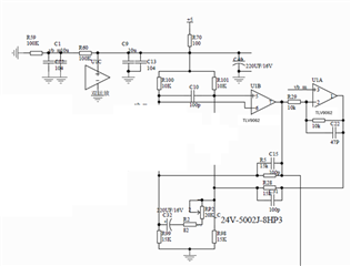
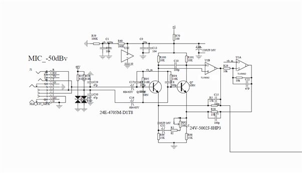
       1. The schematic of the system is as follows:


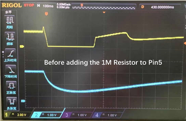
       2.  When the 48V phantom power supply is powered on and off, VB_ M due to the charge and discharge of the capacitor, there will be a drop or climb phenomenon, as shown in the blue waveform in the waveform.


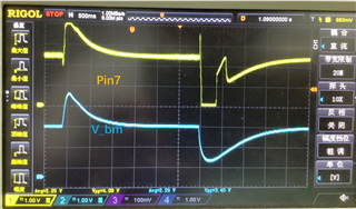
       3. After our test, it is found that when 48V power is off, the audio port output by pin 7 of tlv9062 is rustling. Further grasping the waveform, it is found that pin 7 of tlv9062 will have a peak waveform when 48V phantom power is off, as shown in the Yellow curve below. The pin5 pin6 and VDD of TLV9062 is normal and don't appear dropout which is not shown in the waveform.


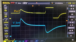
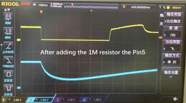
       4. Compared with the normal one without rustle phenomenon, pin7 pin has flat square wave instead of sharp wave when 48V phantom power is off.

       5. The defective chip of TLV9062 was tested by EVM board and found to work normally.

Could you please help to analyze the causes of this phenomenon and provide the solution?


Best Regards

Wesley

  • Hello Wesley,

    I suspect that the input drop causes the NPN transistors to cut off (zero collector current). This breaks the feedback loop; now it is open loop. At that time, the voltage on pins 5 and 6 will be the same. With both inputs at the same voltage, the Vos (input offset voltage) polarity will determine the pin 7 output being fully low (VOL) or fully high (VOH).  

    To stop this, do one of the following.

    1) Get NPN to not cutoff 

    2) Add op amp input bias that remains even if cutoff. try adding a resistor from pin 5 to ground. 10M ohms should work. If not, try 1M to see what that does.

  • Hi Wesley,

    don't apply and remove the +48V phantom power abruptly but via a RC-low-pass filter:

    http://avstomusic.blogspot.com/2012/05/can-phantom-power-damage-your.html

    Kai

  • Hi Kai

    Thanks your reply.

    The website can't be opened. Could you please copy the passage or share other web to me? Thanks!

  • Hi Ron,

    Thanks for your reply.

    1. After adding the 1M resistor,the problem is basically solved. But I can't understand the reason why the R should be added.

    2. Besides, the waveform don't be changed a lot.Only the time of low level is extended.if the bias of amp is added and stable, the output should be high or low level instead of the waveform shown below.

    Could you please explain the waveform and why you give this advice? 

  • Wesley,

    Going back to the beginning, which waveform is acceptable, top or bottom? 


    During the time that output is either VOH or VOL the NPN transistors have no collector current flow. That means the circuit is like this during that time.

    There is no feedback loop. Both inputs at pins 5,6 is 5V. Pin 7 will be op amp open loop gain (very high number) multiplied by the input voltage 0V (5V-5V) plus the op amp VOS (input offset error voltage). Pin 7 = (5V-5V+Vos)*G limited to 0V or 5V. G is big, so output is 0V or 5V depending on polarity (sign) of Vos, Pin 7 can be positive or negative.

    Adding a 1M resistor on pin 5 makes pin5 4.95V and pin6 5V.  Pin 7 =  (4.95V-5V+Vos) *G will always be 0V because the first term is now always negative. Never positive.


  • Hi Ron,

    Thank you for your patient and careful answer. I have understood this principle.

    But there is another question, why is the waveform of some good 2412 pin7 square waves varying from high to low as shown below?

  • Wesley,

    That looks like an overshoot on recovery. Could be do to cap charge delays and the unidirectional current flow of the NPN. Can you try removing C10; capacitors directly across op amp input pins almost always cause more problems than they fix.