This thread has been locked.

If you have a related question, please click the "Ask a related question" button in the top right corner. The newly created question will be automatically linked to this question.

INA901-SP: Decoupling Capacitor Optimal Placement

Part Number: INA901-SP

Hi all, 

I am currently working on a project using the INA901-SP with two decoupling capacitors wired as shown below: 

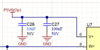
My question is whether I can have one of these decoupling caps on the bottom layer to optimize space as follows:

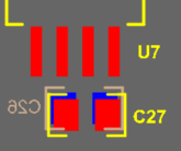
Would this be okay with the 901 or would it be better to have both decoupling caps on the same layer? 

Thank you in advance for considering my question and I hope to hear from you soon!

-Filipe

  • Hi Filipe,

    what counts is package size of decoupling capacitor. The larger the package the higher the undesired inductance. That's why decoupling caps of different values are paralleled, usually. But with todays tiny ceramic high caps such paralleling is no longer needed. Just take one 100...470nF X7R ceramic high cap in 0603 or 0805 package and put it as close as possible to the supply voltage pin. Have the ground terminal soldered to a massive ground plane. That's way better than paralleling ceramic caps of different size and value with all the associated unwanted resonances.

    Kai

  • Filipe,

    Kai is on the money here. As he mentions, the paralleling effect is done to reduce inductance, and tracing through vias between the top and middle/bottom planes will also add to the inductance as the power signal moves between the top and bottom and layers of the board. While most likely not a zero-sum action, this will have some negation on the intended effects of paralleling these capacitors as well. 

    The only additional thing I would add, as rudimentary as it is, is if you do still choose to design your layout in this way, ensure that the power signal passes through the capacitors prior to reaching the input pin of the device. From a layout standpoint, having a satellite capacitor beyond the Vs pin is not as effective as having the signal pass through it for proper filtration to the input pin.