This thread has been locked.

If you have a related question, please click the "Ask a related question" button in the top right corner. The newly created question will be automatically linked to this question.

INA827: INA827 problem

Part Number: INA827
Other Parts Discussed in Thread: OPA192, LM324, OPA325, OPA191, OPA391

Hi team 

Good day

My customer have a question:

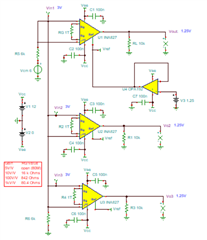
I have 3 INA827 instrumentation amplifiers , all the three reference pins are driven by a single buffer op-amp. The offset voltage I have selected at the op-amp is about 5 or 6 times larger at the Vref pins of these IA's?

Regards

Aosker

  • Hi Aosker, 

    Would you share the schematic with us?

    Based on the available information, I am guessing that this is what you may have or similar. 

    Please make sure that the Vcm input voltage is within the requirements in the datasheet, and input bias current returned path is not floating.  see the image below. 

    Enclosed is the above example and you may check it out. 

    INA827 E2E-1 05202021.TSC

    If you have additional questions, please let us know. 

    Best,

    Raymond

  • customer reply:

    I tested out 1 instrumentation amplifier with a reference opamp, I have used resistors at the input to ground to compensate for bias currents. This seems to work for one instrumentation amplifier and the output and reference are correct.


    However, the moment I connect a second IA reference pin to that same opamp output, I notice the voltage goes up again,

  • Hi Aosker, 

    3 INA827 should be able to drive with a single op amp buffer, however, I do not know what type of op amp you selected. I was wondering if the selected op amp buffer is able to drive all three INA827. 

    Pin 6 or Ref pin needs to be low impedance reference voltage, which is able to source or sink current. If it works with one INA827, I was wondering its output has the current drive 20kOhm (3X 60kOhm in parallel) and the op amp buffer's impedance is low enough to generate a minimum reference error.


    In the case of my simulation, I am using OPA192 to drive the reference pins for all three INA827. Here is the analysis. 

    The OPA192 has a nearly flat open-loop output impedance (Zo) over much of its usable frequency range. Additionally its Zo is very low to start with, about 400 Ω above 10 Hz. When the OPA192 is connected as a buffer and the full loop gain is applied, its closed-loop output impedance (Zcl) is going to be very low. For example, if the loop gain is 100 dB (105 V/V) then Zcl = 400 Ω/ 105 = 4 mΩ. Certainly, that Zcl number will increase as the Aol rolls off with frequency but it will be very low quite a ways up in frequency. Therefore, driving the high impedance REF pin (50 kΩ + 10 kΩ) of three INA827 IAs simultaneously (~20 kΩ) should be fine and result in little error.

    If you have additional questions, please let me know. 

    Best,

    Raymond

  • Hi Asoker,

    would you please be so kind and show a schematic? In electronics the universal language is the schematic. It's hard to say anything useful without a schematic Relaxed

    Kai

  • customer reply:

    I’m trying with a LM324PWR which doesn’t have that output impedance graph mentioned in its datasheet, will the LM324 PWR be able to drive this?

    Also the circuit is the same as the one shown above.

    I’ve noticed adding a high value resistor from the output of the voltage reference op-amp to ground, seems to potentially resolve this issue though,

  • Hi Aosker, 

    Please send us the your complete INA827 schematic. I am unable to figure out why LM324 op amp that is unable to driver the REF pins. The pin has to be low impedance < 5Ohm.  

    I’ve noticed adding a high value resistor from the output of the voltage reference op-amp to ground, seems to potentially resolve this issue though.

    This is not the explanation. An output node of LM324 is a low impedance point, its impedance is approx. 33mΩ at DC in a buffer configuration (verified via simulation). If you draw the circuit by hand and send us a picture of the entire schematic. Or you may send it to my email r-zhang2@ti.com directly. 

    Best,

    Raymond 

  • Aosker,

    The most likely reason for the problem you see is that you operate LM324 in a non-linear region.  LM324 output voltage range extends only up 4V below positive rail: Vout < (V+)-4V -  see below.  This means that for 5V supply the output could only be reliably driven no higher than 1V.  For your reference voltage buffer instead of LM324 please use any rail-to-rail output low voltage op amps like OPA391 or OPA325 (1.8<Vs<5.5V) or higher voltage op amp like OPA191 or OPA192 (8V<Vs<36V).

    The way I see it, the most challenging problem here is understanding your application but so far we don't even know what reference voltage and power supply voltages you use to power INA827 and LM324. As Kai pointed out in electronics the universal language is a schematic but so far you have not even provided basic information like supply voltages needed for us to be able to assist you.  As I like to say a picture is worth thousand words, thus if you need help please don't attempt to describe your circuit in words but instead show us your schematic.