This thread has been locked.

If you have a related question, please click the "Ask a related question" button in the top right corner. The newly created question will be automatically linked to this question.

OPA2333: Oscillation with 470R + 10nF

Part Number: OPA2333

Hello All,

I am using OPA2333AIDRBT as an input buffer of my board. Schematic is as shown below:

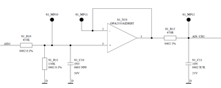
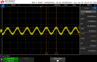
I have tested 80x opamps (40 IC with 2 opamp in each) and I see that 4 of them show oscillation of ~10mVpp at 40kHz. Oscillation looks like this (AC coupled measurement when opamp noninverting pin was at 1V):

My observations are:

  1. This oscillation is continuous and imposed on the DC output of the opamp.
  2. +3.3V supply voltage of the opamp at opamp's supply pin is clean.
  3. I tested two identical boards which are manufactured at the same time. Each board has 40x opamps (20x IC with 2 opamp in each) and different channels oscillate in different boards. This shows that the effect is not coming from the layout.
  4. I see that while each IC has 2 opamps, sometimes one of them oscillates while the other doesn't oscillate when same input is applied. This seems unusual to me, I'd expect 2x opamps in the same IC package to behave extremely similar.
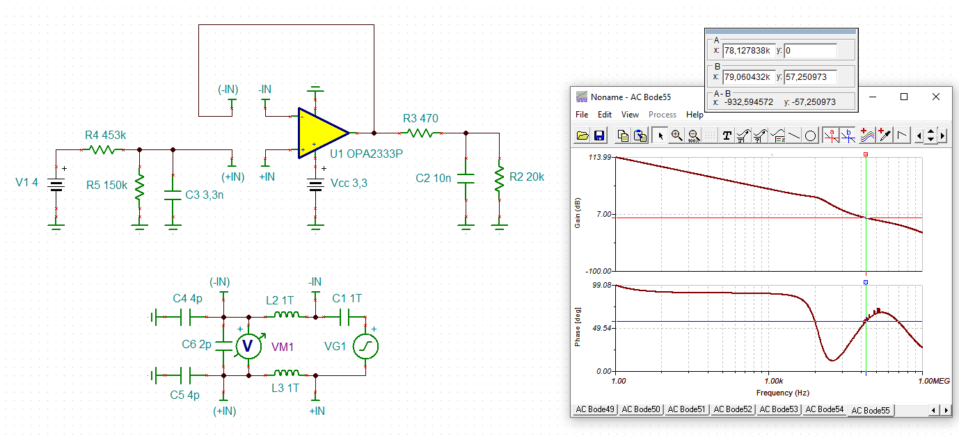
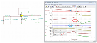
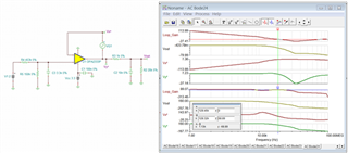
  5. I suspect 10nF capacitance is causing this oscillation however my analyses show that I should have 50-60 degrees of phase margin.
  6. Furthermore, in this other question same opamp was analyzed by TI person and the indicated stability with >400R before the 10nF is mentioned. This agrees with my earlier analyses.
  7. I bypassed the RC filter at the opamp input and applied square wave to the noninverting pin of the opamp. The output didn't show any excessive oscillation, it rises and falls without over/undershooting however the 10mVpp oscillation is superimposed.
  8. There is no 40kHz frequency on my board, so this oscillation is not coming from another source.

Could you assist me with this?

Kind regards,

Zeki

  • Hi Zeki,

    Your description is correct. The instability is caused by 10nF capacitor at the output.

    My guess is that there are additional parasitic capacitance on PCB boards that may not be taken into account and the stability of the buffer circuit is operating near the edge, which it has only 53 degree of phase margin with 10nF capacitive load analysis (also, 10nF +/-20% tolerance may be a factor as well.). 

    With Riso of 470Ω and 10nF, the pole is approx. at 33.9kHz, but the phase starts at approx. 3.39kHz at a decade earlier, shown in blue circles above. The Riso and 10nF did lift the AC phase margin at 0dB, but it will work a slightly better if the pole and zero are shifted to the lower frequency (your input LPF has cutoff frequency configured at approx. 430Hz). 

    I increased Riso from 470Ω to 1kΩ, and I get the phase margin of 68 degree. Hopefully, the Riso will not affect your buffer output.

    Since you have over 40 boards, I want to make the minimum modification. Please let me know if the solution will work for you. Enclosed is the AC analysis simulation per the suggestion. 

    OPA2333 AC Analysis 06012021.TSC

    If you have additional question, please let me know. 

    Best,

    Raymond

  • Hi Zeki,

    these micropower OPAmps can be tricky. Sometimes a snubber at the output may help:

    zeki_opa2333.TSC

    Kai

  • Hi Kai,

    Thanks for the information! I tried 1kOhm instead of 470Ohm and the circuits became stable. Therefore I will not do a relayout of the PCB. But for the next time I will keep your idea in mind.

    Regards,

    Zeki

  • Hi Reymond,

    1kOhm indeed does it. Thanks!

    Zeki

  • Perfect! Good luck Relaxed

    Kai