This thread has been locked.

If you have a related question, please click the "Ask a related question" button in the top right corner. The newly created question will be automatically linked to this question.

INA139-Q1: Problem with INA139

Part Number: INA139-Q1
Other Parts Discussed in Thread: TL074, INA139, INA293-Q1,

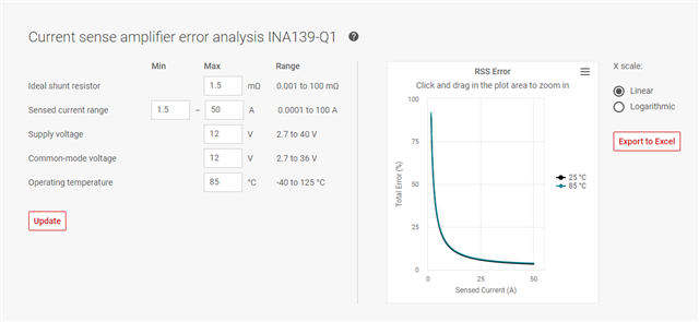
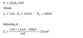
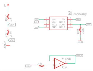
I have a big problem with the INA139-Q, I am using a shunt resistor of 1.5mOhms that returns 75mV@50A. However, I can´t test my circuit with 50 A, so I am trying just with 1.5A, so the differential voltage V+ V- will be ideally 2.25mV, and the output 22.5mV since I am using a 100K load resistor at the output. 

But when I am on the test, it doesn´t work. The output is not stable at any voltage over the load resistor, instead it has some instantaneous peaks. The behaive is similar even if I use a buffer amplifier as TL074 at the output. 

Do you have any suggestion? It is really urgent. 

Thank you.  

  • Sebastián,

    There are a few things I have noticed that are causing your problem.

    Utilizing the current sense amplifier error analysis tool, available at the bottom of the product’s webpage located here, we can see a 88.94% error when driving a 1.5A current. This is shown in the image attached to the reply

    Furthermore, I noticed that the ideal output voltage at 1.5A would result in 225mV, as per the datasheet  Vo equation shown in the amplifier calculations attached.

    Accounting for the offset voltage at the output, we assume the input offset voltage is equal to Is*Rs in the previous equation to calculate the output referred error. This value is shown in the electrical characteristics section of the datasheet.

    If you are able to test the circuit using Is = 50A the output would result in 7.5V. However, for this output to be achieved a power supply higher than nine volts would be needed due to the device’s voltage output swing to power supply and VCM of the inputs condition shown in the datasheet and image attached.

  • Hi Javier, 

    Thank you very much for your response, it was very complete, unfortunatelly I can´t measure 50A with my circuit rigth now, due to my benchmark constrains. Althougth, in our real application, I will require to measure maximum 150A using a shunt resistor of 75mV@150A.

    When I was selecting the current monitor INA139, I was relationing the equations that you just mentioned, but ignoring the error to lower current range. Could you suggest me either better option or configuration to effectively measure this span of current? 

    The main goal was always to isolate the measured circuit to the measuing one. 

    Thank you in advance.  

  • Hi Sebastian,

    can you show an exact schematic of your test circuit?

    Have you properly referenced the inputs of INA139 during the test? Can the input bias currents correctly flow?

    Kai

  • Hi Kai, 

    The following schematic has the configuration that I am using in my tests. And the shunt resistor is under low side configuration respect to the load. 

    The voltage (V+) for the load resistor (REQ) I can adjust it between 10V and 20V DC. And the shunt resistor (RS) is supposed to return 75mV@50A. 

    However, as Javier said, for this current the error will be near to 89%.

    Thank you very much in advance. 

  • Hi Sebastian,

    is GNDA = GND?

    Kai

  • Sebastian,

    With those numbers you want you will need an CSA with low offset as that will be the main error source at the lower currents you are sensing.   For high voltage range similar to the INA139-Q1 please look at the INA293-Q1.  

    Please give me more specification that are important in your application.

  • Hi Kai,

    GNDA is the ground of the measured circuit, but is not the same ground that I am using to refer INA139-Q1. 

    Thank you in advance. 

  • Hi Sebastian,

    keep in mind that there must exist a path for the input bias currents of INA139 back to the signal ground of INA139. You cannot let the inputs of INA139 entirely float.

    Kai

  • Hi Kai, 

    Thank you for your response, so Should I use, for example, one resistor with high impedance (1MOhms) to ground for each input of the INA? 

    Sebastián, 

  • Hi Sebastian,

    the INA139 is intended to have GNDA = GND Relaxed

    Kai

  • Sebastian,

    For me to suggest another CSA(Current Sense Amplifier), I will need some more information on what is required for your application.  I pointed out that you will need to worry about VOS if you plan on having good accuracy at lower currents of your range and one of the CSA that I think match as close as possible to the INA139 in terms of speed and lower VOS.  Most of our CSA product pages have the error calculator for you to place your information into it and calculate the error over your range.

    Also I agree with everything Kai says above but I am taking the approach with an alternative part.  Even with an alternative part the information about the GND is consistent with other CSA.  This issue with the 1M is the two GND could be different and you could violate Absolute Max Ratings of the CSA causing issues.

  • Hi Sebastian,

    can you explain how GNDA and GND are connected to each other?

    A complete schematic would be helpful.

    Kai