This thread has been locked.

If you have a related question, please click the "Ask a related question" button in the top right corner. The newly created question will be automatically linked to this question.

THS4521-HT: Input overvoltage protection

Part Number: THS4521-HT
Other Parts Discussed in Thread: THS4541, THS4521, THS4551, THS4561

Hi There

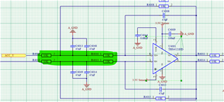
I'm using a THS4521-HT running off a unipolar 0-3.3V rail

There's a user case where the THS4521-HT could see a +/-12V signal on one of its inputs on rare occasions. As I have resistors in between the +/-12v signal (each one of the highlighted parts is 10k) and the op-amp inputs would I be correct in assuming the part won't be damaged as the 12/20k = 600uA input current is less than the maximum 10mA in the datasheet? (I don't need to red the signal in this scenario, its a fault condition)

same question in the scenario where the THS4521-HT is unpowered and there's a 1/-12v signal.

Kind Regards

Martin

  • I sometimes add protection diodes to be sure, as per this example I put into the THS4541 datasheet, Need to add their capacitance into your validation sims. This particular circuit came out of a collaboration with Dallas Logic and was implemented as a board for sale. 

  • I see we have talked these things over a bit in the past, 

    https://e2e.ti.com/support/amplifiers-group/amplifiers/f/amplifiers-forum/793052/tina-spice-ths4521-ht-input-common-mode-problem-or-tina-spice-model-error

    There are so many of these, I can't really remember them after a few months, 

  • Hi Michael

    yes you have helped me out with serval questions in the past, the same project as the link you have posted - everything got paused due to covid, restarted now.

    I wanted to avoid using diodes as I'm incredibly short of PCB space - My default is not to add the clamps as I'm pretty sure an overvoltage condition is ok as long as the current is limited. I just wanted to post the question in case somebody out there says I can't do that.

    kind regards

    Martin

  • Also Martin, while it may not matter in your application, be aware that this phenomena occurs in the THS4521 - I would suspect you have a relatively low volume app, if this kind of issue is critical, prescreening might be prudent - updated test preamp is included in this thread, 

    https://e2e.ti.com/support/amplifiers-group/amplifiers/f/amplifiers-forum/963447/ths4551-flicker-noise/3559868?tisearch=e2e-sitesearch&keymatch=ths4521%252525252520popcorn%252525252520noise#3559868

  • Hello Martin,

       The input current shouldn't be the issue here because of the input resistors which you have already calculated to be around 600uA. This E2E post (link) summarizes the second case which is violating the differential input voltage max rating especially when amplifier is unpowered.

    Thank you,

    Sima

  • Hi Martin,

    preventing damage is only one side of the coin. Another issue is: What is the circuit doing when overdriving the inputs during normal operation. Does it come back from the overdrive and continues to work properly? Or does it show some sort of latch-up? Maybe not a room temperature but at elevated temperatures? Don't understand me wrong, I'm not saying that latch-up will occur. But in a professional application I would avoid such unpredictabilities right from the start. If the input signal comes from the outer world, I would add clamping diodes in any case Relaxed

    Current limiting resistors might seem to be sufficient here. But keep in mind that with only a current limit resistor you will inevitably bias the internal circuitry of THS4521 in the situation of input overdrive, if you want or not, provided the input overdive exceeds 0.7V (see the absolute maximum ratings of datasheet). With an additional diode clamp, on the other hand, you can limit the overdrive to such a low level that no or no relevant current will flow into the THS4521 and that the internal circuitry is not or not relevantly biased. This is a huge difference.

    Kai

  • Hi Kai / Sima

    Thanks for the messages, 

    An over-voltage condition could happen in two scenarios; 1) an instrumentation amplifier is driving one of the THS4521 inputs powered from a +/- 12V rail which will be on before the THS4521 supplies come up - I wouldn't expect a 12v signal but you never know. 2) a +/-12mA signal is driving the instrumentation amplifier, the signal of interest is +/-4mA and the instrumentation amplifier gain has been set to make this full scale to the THS4521 - there could be short burst (10-100mS) scenarios where the overall input is between 4 and 12mA for short durations.

    Reading the posts in the links below adding clamping diodes would be best but I simply can't fit them on the design without a heavy about of PCB layout and tracking rework, I'm at the prototype stage so if there is something amiss hopefully I'll catch it. But I think the various posts concludes keeping the current to less than 10mA should be ok and the ESD diodes clamp the differential inputs preserving VID. for reference here's a link to a similar post.

    e2e.ti.com/.../143225.aspx

    Hi Michael

    thanks for the comment on flicker noise, I'll keep an eye out for this whilst prototyping. I have 8 of these amplifiers per board and will be making several prototypes, so hopefully I have enough samples to see it maters

    Kind REgards

    Martin

  • Sure Martin - looking a bit more broadly, perhaps that Hi-Rel group that did this HT version should think about adding a newer FDA to those options - Like maybe the THS4551 and/or THS4561. Those do come in the very small 10pin QFN "RUN" package, but not sure that can handle the HT range.