A related question is a question created from another question. When the related question is created, it will be automatically linked to the original question.
If you have a related question, please click the "Ask a related question" button in the top right corner. The newly created question will be automatically linked to this question.
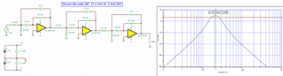
OPA2156: filter design tool single ended power supply required
1. Use the filter-design-tool above to get the Bandpass performance you want, such as filter's gain, inverting vs. non-inverting, bandpass region, filter topology etc..
2. Once you get the filter circuit you want, you may create a design circuit from the tool above,
3. I will convert the suggested BP filter design from the above, and duplicate and simulate it in Tina-TI.
4. Fine tune the filter with a single positive supply voltage rail and check out the final BP performance.
5. Once you are satisfied with the simulated filter performance, I would build it and verify the performance on a bench or via PCB.
So I see we created a virtual ground. I do have an 8 volt rail available and I could create a virtual ground between that rail +/- 4 volts. However I need to think on this as the Diseq controller that I am feeding into will be referenced to a system ground. Maybe I just AC couple the output to system ground reference with a series .1uF cap.
Thoughts on that? I guess I am confused as to why I can't do this with a single rail and no virtual gnd.
bias the +inputs of OPAmp at middsupply and insert >100nF caps in front of each resistive voltage divider. You might also want to insert such a cap at the output of last OPAmp.
Thoughts on that? I guess I am confused as to why I can't do this with a single rail and no virtual gnd.
It is Vcm bias issues at input of op amps. You may do what Kai is suggested or provide a slight negative voltage rail at Vee, like LM7705 (low noise negative bias generator via switched capacitor charge pump). It may work, at least the simulation indicated that it may work.