This thread has been locked.

If you have a related question, please click the "Ask a related question" button in the top right corner. The newly created question will be automatically linked to this question.

OPA627: noise simulation question in section 8.6 of Precision Lab video

Genius 3870 points
Part Number: OPA627
Other Parts Discussed in Thread: OPA2205, OPA192

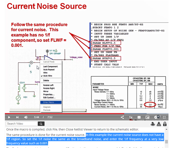
Hi there, When watching this 8.6 video,  it  mentions at 5:44: 

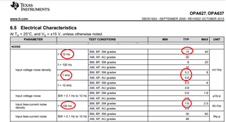
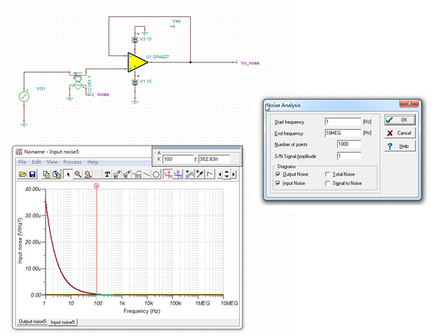
In this example the current noise source does not have a 1/f region. So set the 1/f noise the same as the broadband noise, and enter the 1/f frequency at a very low frequency value such as 0.001.

May I ask why can we do so (as the red text)?  Thanks !

  • Hi Rust,

    where do you see issues?

    Kai

  • Couple of things here Rust, without looking at that video, I think they are explaining how to add a couple of external noise macro's to a model that might not have the correct noise model internally. I just tested the OPA627 2019 model update and it has what looks like a good input current noise in the TINA model - so you don't need to add anything externally, Over time, the current noise for JFET (or more precisely DiFet here) was changed to show an increasing value going up in frequency, and that is in the 2019 TINA model, Just putting a current meter into the input and running an output noise sweep shows this - that 1.6fA matches the datasheet, 

    As for the macro's - they are set up to look for a flatband value and some value at lower frequency that is higher to set up a 1/f model. In this case, just putting in an equal value at very low F fakes it out to give you a flat spectrum from the macro, but you don't need it anymore with the latest OPA627 TINA model.

  •  Hi ,

    Michael has replied your inquiries in great details. 

    Q: May I ask why can we do so (as the red text)?

    It is not clear what is your question.  8.6 video is talking about building your own noise model (noise voltage source, noise current source with a generic op amp). 

    This is how script commands work in a macro model. 

    If you enter a command wrong, the interpreter software is not going to interpret or understand a command correctly. In other words, you have to follow .PARAM command exactly as it is defined. 

    In order to simulate the voltage and current noise behaviors accurately in an op amp, you can customize a known op amp's (e.g. OPA627, OPA192, OPA2205 etc. ) noise behavior with the following Tina model. You can edit and enter the voltage and current noise behaviors per a known op amp datasheet specification via the Tina model below (voltage noise + current noise + generic op amp with correct op amp gain, GBW in frequency responses).  

    If you need further assistant, please let me know. 

    Best,

    Raymond

  • Setting Inoise .PARAM FLWF=0.001, without specyfing .PARAM NLFF, sets the 1/f input current noise spectral density to the same value as broadband current noise, NVRF, and that's what you want for 1/f input current noise in most CMOS and JFET input op amps like OPA627 where broadband current noise, set by .PARAM NVRF=1.6 extends into low frequency. Thus, the OPA627 macro-model properly simulates the input current and input voltage noise spectral densities - see below.

    OPA627 Noise.TSC

  • hi Marek. I think Michael has answered my question "In this case, just putting in an equal value at very low F fakes it out to give you a flat spectrum from the macro".

    By the way, I download your attachment tsc file and run it, but the results (as below) seem not as same as your snapshot. Did I missed something? In my results, Voltage output noise5 is correct(match with datasheet), but the current noise seems not .

    And my Y-axis is linear but your results is in LOG, is there some way to set this?. TINA vesrion is 9.3 downloaded from TI webpage.

    Thanks!!

  • In you simulation window you show at 100Hz Vnoise of 362nV/rt-Hz instead of Inoise - thus I believe you look at a wrong curve. Go to View at the top of sim window and separate the two curves before placing cursor. Having said that, there is something wrong with your noise simulation where Vnoise at 1Hz is 35uV/rt-Hz instead of around 55nV/rt-Hz (~1,000x higher) - this is most likely caused by the problem with your default Analysis Parameters values (see below).

    In order to put the vertical axis on log scale, click on vertical axis label and change it to log - see below.

  • Hi Marek, as you adviced I got the correct displayed curves as below left picture.

    Another question to consult. When I choose "Input noise" box in Noise Analysis setting(as red circle in right pic) , the Input noise curves of two nodes are displayed. The input noise of Inoise node(yellow rectangle) seems very large, Why?  Thanks again!

  • When you pick output noise, the simulator showns Inoise and Vnoise as shown below - this is what you should use.

    However, when you pick input noise box, the simulator shows the equivalent input voltage noise seen by Vin (for G=1, it is the same as output Vnoise) while for current noise it converts Vnoise across the close-loop output impedance into equivalent Inoise - see below. Therefore, this Inoise is not a true input current noise but rather it is a calculated value what it would have to be to generate Vnoise seen at the output.