This thread has been locked.

If you have a related question, please click the "Ask a related question" button in the top right corner. The newly created question will be automatically linked to this question.

INA180: Looking for the right current sense board for 0-5A DCC or a 12V square wave

Part Number: INA180
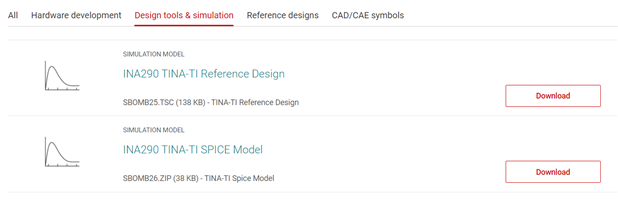
Other Parts Discussed in Thread: INA290, INA280, INA281, TINA-TI, INA223, INA226, INA228, INA254, INA240

Hi,

I've been through the forum. My first question is that I see a calculator that will create graphs. Is that open to the public? Secondly here is my need.

12-19V DC on the power input to an H-Bridge Motor Controller or...

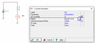
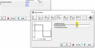
12-19V bi-polar square wave with 58 and 115us widths at the output

0-5A or if possible, 0-10A

The ability to sense a current of 50mA and be able to measure a 60mA 6ms pulse above that level (100mA)

So the key things are the low end sensitivity with low noise to sense that low current, fairly short pulse. The 181 seems iffy because of its large amount of noise. It seems to have 130mA of noise at 0V. Putting a 470nF capacitor on it I think reduces the noise down to 30mA or so but really slows it down. I'm not sure I can accurately read a 60mA, 6ms pulse.

There is no need for a schematic, because if I measure DC at the input, I am just measuring the power used by the motor controller (H-Bridge) and whatever load it is connected to. On the output, I am simply measuring the current of a bi-polar square wave that is used to generate a high power digital signal. It is not directly driving a motor. We can rectify the voltage of the signal to power something and pick off the 1's and 0s of the bipoler signal to control it.

Any help is appreciated. I have 2 outputs, so it would be possible if I want to use 2 circuits, I could use one that reads 0-1 or 2 A and another that read 1-5 or 1-10A. Lots to engineer through ;)

  • Hello Mr. Decker,

    Thank you for the detailed requirements and background. I am looking into this and will reply back shortly.

    Sincerely,

    Peter

  • Hello again,

    When I try to solve all these possible configurations I sometimes just resort to simulation. I think using one of the INA280/INA290 or INA281/INA93 could be could for the 50mA DC measurement. The free TINA-TI and PSPICE for TI downloads are great to quickly analyze many of the errors (DC sweep, VCM transient, total signal noise/SNR).

    We have some devices that measure voltage pin (INA223, INA226, INA228), so you will have to defer to those datasheets to understand if their noise work for you.

    Note that a switching VCM (12V to 19V) will cause output disturbances on most amplifiers (see my second attached sim). If this can be a concern, then using the INA240/INA254 are great options because of their enhanced PWM rejection (high CMRR).

    INA280_IDC_meas.TSC

    INA280A4_VPWM_meas.TSC

    Hope this all helps.

    Peter

  • I just want to be clear that the H-Bridge is powered from just one voltage that is dependent on the permanent setup. Some setups may be 12V and some may be 14V and some may be 19V. 90% of users will be 12V. That means that we will generate a bipolar signal of 1s and 0s  that will swing +12 and -12V. That is 24V peak to peak. And you have been a big help. Now I have to learn TINA-T1 to see how to simulate this. I can modify what you have already generously given me. I see you set the voltage at 14.5 volts, but I don't know how to set it to 12V and have the graph show +12V to -12V instead of 12V to 19V.

  • Hey Fred,

    Here are a couple screen shots on how to edit a voltage/current source (generator) in TINA. The screen shots shows me editing a current source to +/-12A at 8kHz, but it is the same process if you edit a voltage source to +/-12V at 8kHz.

    To perform a transient simulation, simply press Ctrl+Alt+T. This open the transient sim window where you can adjust how long the simulation should last.

    There is not much strict simulation education material on Ti.com, but we do have a large compendium of useful signal chain analog circuits that may provide some more insight on how to set up the simulation. You can download this booklet here for free.

    https://www.ti.com/design-resources/design-tools-simulation/analog-circuits/overview.html

    To find some reference designs for motor current sensing, you can search our designs here and type motor into the key word search field:

    https://www.ti.com/amplifier-circuit/current-sense/analog-output/reference-designs.html#search?famid=3172

    This application note also shows how to manage using simulation for motor current sensing in body control modules.

    https://www.ti.com/lit/an/slya047/slya047.pdf

    Sincerely,

    Peter

  • Hi Peter, What great support! Thank you so much. The rest is on me. I need to read and have to learn yet another tool, but I'm not complaining ;) It is similar enough to other spice type tools and will save me troubles in the long run.

  • One more question. I can't find any of the parts you mentioned in the list of parts for TINA. Even the INA280A5 is not listed anywhere. I wanted to try the 20V/V one and the INA290, etc.

  • Fred,

    No worries! Our spice models are located in the product folder under the design and development tab. You'll need to select the "Design Tools and Simulation section. Our SPICE models have all the gain variants present inside the model, and you simply need to select which one you want and delete the rest. 

  • Sorry, still lost. I expected that the TI version of Spice (Tina) would have all the TI chips in it. The examples I was given above have the INA280A5 in them. I can model it. I would have expected that in the ribbon bar of Tina after clicking on the "spice macros" and clicking on the "difference amplifiers" button or the "current shunt monitors" button everything would be there. In fact under 2 of the buttons there are all sorts of devices that start with INA, but none of the ones I was recommended above. I double-clicked on the INA280A5 on my schematic and see it is stored in C:\Users\a0282827\AppData\Local\Temp\DesignSoft\{Tina9-TI-04052019-143025}\INA293A1. The INA293A1 doesn't even match my INA280A5, so I have no idea what's going on there.

    So  I think that I must have to download a "reference design" and a "Spice model" as mentioned in the previous message and install them somehow. I tried to follow: " spice models are located in the product folder under the design and development tab. You'll need to select the "Design Tools and Simulation section." I've tried this domain and ti.com. I can't find any models or menu. The "design tools and simulation" takes me here: https://www.ti.com/design-resources/design-tools-simulation.html. It looks nothing like tie image above where I can load Tina spice models.

  • Hey Fred,

    So the pre-loaded IC macro libraries for TINA-TI are outdated and are not updated every time a new model is created. Personally, I do not use the pre-loaded model libraries very often unless I'm looking for an older device or an older version of an older device. I always download the model from the product folder's Design Tools and Sim section (https://www.ti.com/product/INA293?keyMatch=INA293&tisearch=search-everything&usecase=GPN#design-development##design-tools-simulation). Then I store all my downloaded macros in my own personal library folder for TINA software. We apologize for the inconvenience.

    You could also download the model's reference design, which is usually just a TINA sim file with the model and some circuitry already set up for convenience and then copy and past the macro from the ref design to your simulation.

    About the storage location you see for the INA280A5, please ignore this. This file path has nothing to do with where the model came from or where it is stored. As long as you can go inside the Macro to view the core netlist and see headers mentioning INA280A5, then this is all that is needed to confirm the model is what it says it is.

    Hope this helps.

    Best,

    Peter