This thread has been locked.

If you have a related question, please click the "Ask a related question" button in the top right corner. The newly created question will be automatically linked to this question.

THS4561: Doesn't seem to allow temperature sweeps in PSPICE

Part Number: THS4561
Other Parts Discussed in Thread: THP210, THS4531A, THS4551

Has anyone encountered this "mystery"?

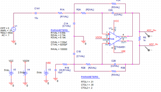
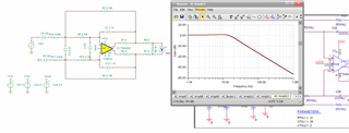
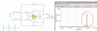
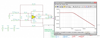
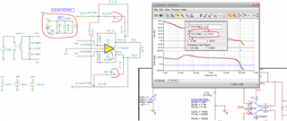
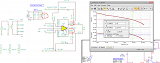
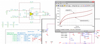
So I have a pretty simple 2nd order LP ADC driver using the THS4561, and it doesn't seem to converge on the second temperature of a multiple temperature sweep. You can run the ckt at any temperature and it converges fine, and yields believable results (for the test i am simply running a AC sim to make it fast, but others do the same thing).

But if you select temperature sweep and specify multiple temperatures, it will invariably not converge on the second temperature. To add to the complexity....it will run a sweep IF  VCC=6V, VEE=-6V, VOCM=0V (as the example schematic on the model download is set), but will not converge if you set it to VCC=6V, VEE=0V, VOCM=3V (i.e. run it single supply. I have archived design as zip and can upload if needed.

thanks in advance

cm

  • So Charlie, sim mystery aside, what parameters have you put a tempco on - the external RC's? The actual TINA model for the THS4561  probably does not support much in the way of temperature variation except perhaps on the DC error terms. Looking inside the model netlist, yes only input Vos drift is modeled it seems, 

  • Michael:

    The whole circuit has some FET and BJTs and passives. They all have tempco for various parameters. I am not really concerned that the 4561 only models the input offset voltage with temp, but with it in the circuit a temp sweep hangs up the simulator, for reasons unknown to me. And as you point out there is NO reason that the model should really care other than one term. I have removed all other components but the 4561, and its support passives...still hangs as I describe.

  • Hi Charlie,

    that a simulation collapses when having a big circuit is normal and happens very often. I recommend to divide the circuit into smaller subcircuits and simulate them separately Relaxed

    Kai

  • Hi kai:

    Thanks, and yes that is a valid method, and I do it quite often, BUT the "predecessor" ck which used a different OA from another vendor did not hang the sim on temp sweep. Also removing all other ckts but the oa and support passives still hangs it as I describe. 

  • If you are using TINA V9, you don't have a lot of analysis options to play with, I just opened those on my 2nd computer, go to Analysis, at the bottom options, and try switching to trapezoidal integration. 

  • I am using PSPICE, but that's a good suggestion...I'll check my sim settings for trap integration. I wont get to it immediately, other less interesting things got in the way. But I will let you know one way or the other.

    cm

  • Also, I just took the starting THS4561 reference design and went into mode, selected temperature stepping over 15 steps 0 to70deg and it ran fine, these AC sweeps are all on top of each other so you can't see any difference, but it did run in V11. 

  • Try this....set VCC to 5V, VOCM to 2.5V, VEE to 0V put those R's and Cs around it, do an AC to see that it works, then step temp 0,27,55 C. The original trila ckt shipped does in fact step just fine, this doesnt. Note that I have removed all temp-co from the passives so technically you should get 3 identical graphs, a filter peaking at about 9KHz.

  • Ok Charlie, so I was redoing the front page MFB filter some months back - I had done it originally before the final model was out and it definitely has some phase margin issues that needed attention, Anyway, I modified the final file I had to your values and it would not converge - then I went to trapezoidal and Davis KLU matrix solver (v11 only option) and it ran, giving this response - looks ok I suppose, 

    I suspect it is marginally stable - not converging is a clue, 

    Here is the spot noise out through 200MHz, quick way to check looking for a spike, 

    Yea, this has an issue which might explain your convergence issues, 

    In that directory where I was tuning this, I had sort of a running commentary for myself, here that is, talks about how to get better phase margin in this circuit. 

    THS4561 front page MFB stability issues.docx

    Also, not sure where you are getting your MFB RC, but I have enhance loop gain flow, easy to run - here are your current targets, You can use a lot slower part incidentally, not sure if the THP210 has enough input headroom - or maybe the THS4531A, 

    With these RC numbering, from an earlier app note I did a long time ago now, 

    In any case, putting these targets into the full enhance design flow, gives these best fit RC values, 

    These, by themselves will not help the phase margin - those tuning elements will. But it will reduce the in band integrated noise. 

    And of course looks about the same as before, I scaled the R's down for noise, but they can go back up just as easily, 

    I am sure the resonance is still there, but here is the LG plot I am always looking at here - trying to reduce the NG peak if possible, 

    That extremely high min LG at Fo comes partially from using a very fast amp in a low frequency design, 

  • Michael:

    First off thanks, I will get back to this Monday. At the risk of showing my ignorance, what is "enhance loop gain flow" is that a tool, a method, or what?

    cm

  • The enhanced loop gain flow was the result of many years trying to improve the MFB design flow, essentially - an infinite range of RC combinations will give you the desired shape - however, you can tilt the solutions towards a lower noise gain peak which has several benefits. I started this with an app note at TI, then improved it and used it for the Intersil online design tool, and have continued to improve it in small ways over the last few years. 

    Here is the original app note, and it is not super clear on how to use this info, and, the cubic coefficients to include the op amp GBP are not correct, I use the cubic to try and adjust the RC for the GBP of the op amp, works pretty well these days. 

    https://www.ti.com/lit/an/sboa114/sboa114.pdf

    Steve Taranovich was bugging me for content, so here I fixed the coefficients for the cubic, 

    https://www.planetanalog.com/include-the-op-amp-gain-bandwidth-product-in-the-rauch-low-pass-active-filter-performance-equations/

    And then once you kind of internalize the peaked noise gain concept, kind of easy to get a min GBP methodology, I use 20dB right now as min set a target for the solution op amp - that comes from running +/-20% GBP variation in various test designs and seeing the added spread over RC spread. 

    https://www.planetanalog.com/use-true-gain-bandwidth-product-to-estimate-required-margin-in-active-filters-insight-13/

    If I go back a little further, I have a few articles on testing spread via RC tolerances on the MFB, The design flow I developed also is going in the direction of reducing that for a given RC tolerance. 

    I think the clearest exposition of how you manipulate the ratios in the MFB to reduce the NG peak was in a slide deck for National Instruments. I am pretty sure I have never published that. 

    I think your immediate issue though is that you are marginally stable, that can be fixed pretty easily as per that word file - if you have post RC filtering to the ADC (most folks do) put that into your sim first. 

  • Morning Charlie, little more time to pursue this, yesterday I did a quick output spot noise sim to highlight a possible problem in your current circuit that might be causing your convergence issue (very low phase margin) that is your immediate issue, and would be a production issue down the road. Anyway, I took the LG sim file I was using for the front page MFB redesign and modified it to your values, This looks like a lot, but really just setting up the FDA with inductive feedback and then injecting the diff signal in through caps - common LG sim trick, I have set your load to 1kohm (which I suspect needs to be updated before you complete this investigation) and the phase margin improvement elements to zero - this is the 2018 model - I think original RTM. 

    Anyway, yes, your nominal circuit shows -19deg phase margin (the sense meter in the upper left which is including the open loop diff input C of the FDA is rotated to report phase margin directly) so you in theory are oscillating. 

    The tuning elements (which will need resetting if you add an RC load) are an added diff C across the inputs to shape the high F noise gain up from the 1 caused by the MFB feedback C and the added buildout R's inside the loop to isolate the resonant Zout from the feedback C, 

    So yes, doing that pulls the LG=0dB way back to 11Mhz and gives 25deg phase margin, so going the right direction - you could add these elements to your stepped temp Pspice sim and see if it now runs ok indicating the convergence issue was in fact an unstable circuit issue. 

    Here is this latest LG file in TINA V9, again this is just a start, I really suspect you have a post RC if driving an ADC which will need retune, And then there is all that extra stuff on improving the in band integrated noise. 

    MFB LG for THS4561 original moses ckt.TSC

  • And then, going to closed loop to look at in band integrated noise, here are the original RC values looking up through 1MHz, and then the improved RC I sent yesterday - this reduced integrated noise is mainly just the lower R values, but there is an incremental improvement with the lower NG peaking aspect of the enhance MFB design flow, 

  • First off Michael....Thanks a million for the first rate education! I mean it, although I am still digesting it. Now I assume (we know what that word is composed of) that the spreadsheet you used is based on your App report SBOA114, if not correct me because I will construct one, unless the one you have is available. I will also look into a part that is a bit slower, you are correct that I don't need that speed and its inherent problems.

    BTW you asked where my values came from, they are synthesized from Electronic Filter Design Handbook, .5 dB 2nd order Cheby. But no, I did not include Opamp GBW and Aol as you did.

    cm

  • You bet, yes I think the THS4531A is plenty for your app. It also has a reactive output Zout, and if you are heading towards adding a post RC to the ADC (I usually do that as the real part of a 3rd order filter) add that early on. Thanks for compliment, the tool I have has evolved through a couple of companies and is always a work in progress. I heard through the grapevine that the ADI FIlter tool was trying to encompass what is in that app note, and they definitely do a GBP adjust in their flow. Using a THS4551 would not matter on that, the THS4531A more so. 

  • Incidentally, a few years back I had some time on my hands and did a couple of survey articles exercising the available tools then available (end of 2017) the details may well have changes by now, but this will give you an overview of some of the things to look for, 

    https://www.edn.com/testing-op-amp-tools-for-their-active-filter-design-accuracy-and-dynamic-range/

    And the 2nd part, 

    https://www.edn.com/active-filter-design-tools-shootout/