This thread has been locked.

If you have a related question, please click the "Ask a related question" button in the top right corner. The newly created question will be automatically linked to this question.

INA186-Q1: Slew Rate Exceeded

Part Number: INA186-Q1
Other Parts Discussed in Thread: INA240, INA186

Hey Team,

I have a customer that is looking to use the INA186-Q1 in a 0 to 40V PWM application with a slew rate of 9V/us.

What issues might arise in this application since the datasheet states a typical slew rate of .3V/us?

Does this mean the INA186-Q1's output will go from ~0V to FSR in ~133us rather than ~4.4us?

40V / .3V/us = 133.33us

40V / 9V/us = 4.44us

Best,
Dajon McGill

  • Dajon,

    Let me clear up some things.  You have inputs and output parameters mixed.

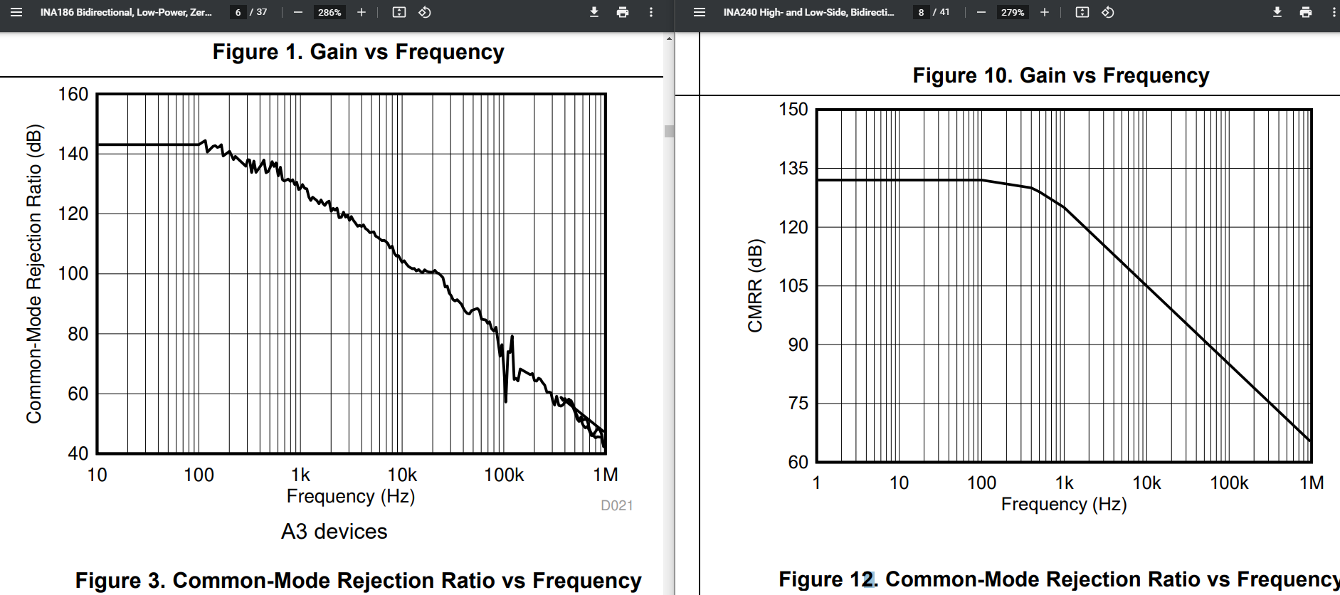
    The PWM is the input signal and a assume this is only a VCM change and not to much of a Vsense voltage changes.  The slew rate on this matters for how the device will filter out the VCM change.  This is normally seen in the AC CMRR curves.  Normally our AC CMRR curves do not address high frequency changes like a PWM input signal which has much higher frequency components.  That is why the INA240 was designed to mitigate high transient signal from the Common Mode input voltage.  CMRR is rejecting this signal at the input. 

    The slew rate of 0.3V/µs is only regarding to the output of the INA186.  So the two slew rates are somewhat not related.  They are in a way that when there is a large common mode spike that disturbs the input side will eventually get feed to the output and then after some time the INA186 will try to recover.  So this limits the time for the out to recover.

    So for slew rate this is normally done form 10% to 90% to avoid any non-linear issues and saturation at the input or output stages and does not include and settling time device.  This will all be output limited.

    So for this device the output is limited to 5V.  So if you were stepping the output from 0 to 5V the slew rate would state it would take 16.7µs but this is not what will happen as you would require time to settling and the slew rate is not defined from 0V to 5V.  So I would guess it would be somewhere around 40µs.

    I would not recommend the INA186 for a high common mode change at the input.

  • Hey Javier,

    Thank you for the clarification!

    Are you saying that you would not suggest the INA186-Q1 for this application primarily because of the lower CMRR?

    Also, I'm now noticing that the INA186-Q1 doesn't have a spec for AC CMRR. Is there a significant difference in these two devices in terms of CMRR that I am overlooking or is it simply not characterized in the datasheet (whereas the INA240 is)?

    Best,
    Dajon McGill

  • Dajon,

    I would not recommend the INA186 because of the AC CMRR.  A PWM signal has many high frequency components that causes errors.  The INA240 has circuitry in order to deal with this.  The INA186 has two things against it.  It is slower and it has worse AC CMRR.  So even when you get a transition in the VCM it takes longer to recover.  Below is an image comparing the INA240 and INA186 AC CMRR although the special circuitry of dealing with this PWM VCM is not shown in this plot for the INA240.  This is explained in the first section of the datasheet.