This thread has been locked.

If you have a related question, please click the "Ask a related question" button in the top right corner. The newly created question will be automatically linked to this question.

LM393: comparator + RC delay circuit

Part Number: LM393

Dear Expert,

Good day!

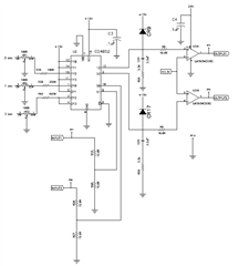
Our customer designed a comparator + RC delay circuit as shown in attachment:


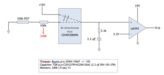
(I have eliminated few details for clarity)
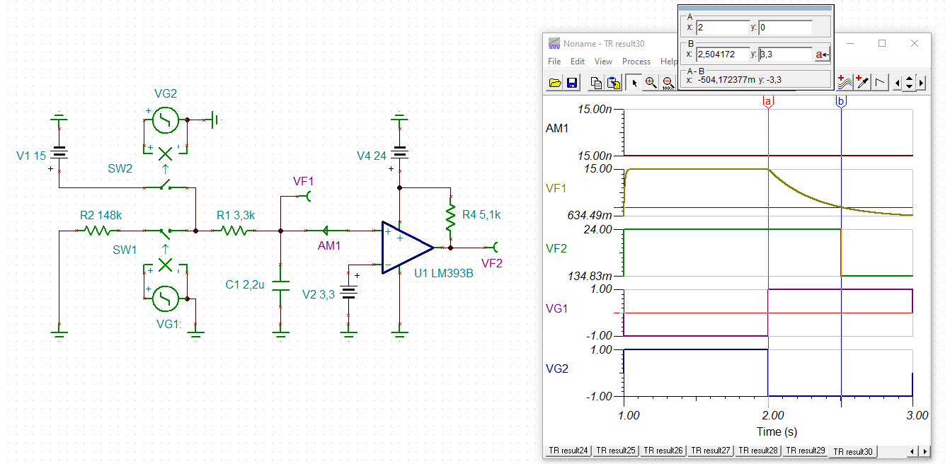
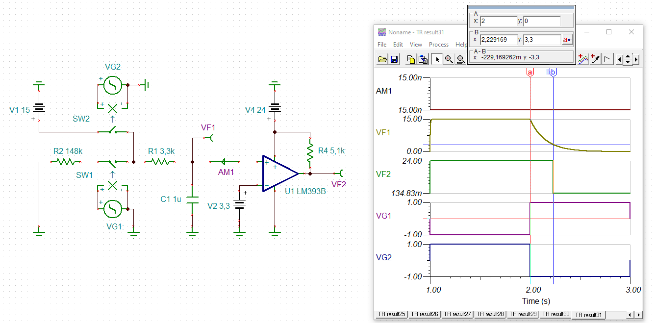
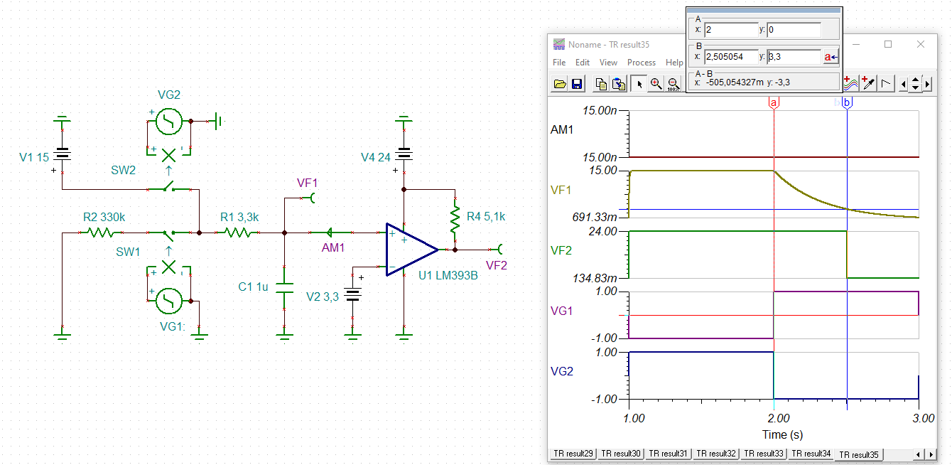
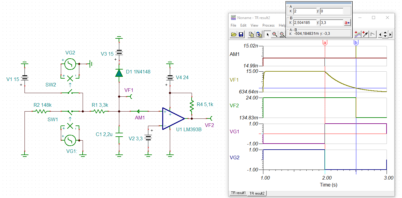
Basically the cap charges during one of the MUX selection and discharges during the other selection.
Depending on the potential across the capacitor, the out put of the LM393 comparator goes to 24V or 0V.
The RC was designed such that it takes 0.5 sec for the capacitor to discharge from 15V to 3.3V. Simulation results match.


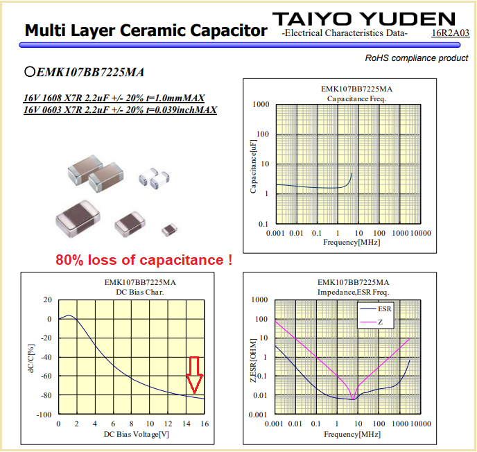
However, once this circuit was implemented in PCB, even with extreme values of POT, we couldn’t reach the designed delay.
In fact, the supplier had to increase the series resistor to 240k to get a value close to 0.5 sec!
Do you know why this happens? Could you let me know how to fix the issue?

Best regards,


Leon.liu

  • Hello Leon,

    Did you prototype the circuit first? Or simulations only?

    Did your simulations include the comparator bias current? Or leakages of the switch? Or Ron of the switch?

    Was the 100k resistor time shorter or longer than 0.5sec?

    Is the capacitor charging up to the full 15V within the expected time?

    What is the supply voltage for the CD4052?

    Can you share the eliminated details? The full Schematic?  Sometime the problem lies elsewhere..

    Is it possible to get a scope shot of the entire charge/discharge sequence?

  • As far as I can see, this circuit was designed for a discharge current of 75 µA, and your problem is that the capacitor discharges too fast.

    There appears to be a current leak somewhere. Does the capacitor keep its charge when you entirely disconnect the POT and/or the mux?

  • Leon

    we will await your response.

    Chuck

    Thanks for jumping in to assist Clemens.

  • Hi Leon,

    X7R caps come with very high manufacturing tolerances and show an extreme voltage dependence of capacitance. Here a typical 2µ2/16V/X7R cap:

    I would take a plastic foil capacitor in your application.

    Also, rethink the position of 3k3 resistor Relaxed

    Kai

  • Thanks Kai for contributing as well.

    Chuck

  • Hi Team,

    Here below is the feedback from the customer. Please help to support.

    ----------------------------------

    I only simulated the circuit. (In fact, an initial version of the circuit (with relays - not MUX and different set of RC) was tested in breadboard - and it worked fine). The current/latest design was simulated in LTSpice. The simulation used the LTSpice model for LM393, however I used an equivalent MUX (available in lib) 

    100k resistor was shorter than 0.5 sec. 

    The capacitor charges to 15V within expected time.

    Supply voltage of CD4052 is 15V.

    Full schematics which has 3 more similar circuits attached herewith.

    I will try to get the scope shots.


    @Clemens, you are right capacitor discharges too fast, the circuit is currently in a PCB and hence, haven't checked if the capacitor retains charge once the POT and MUX are disconnected.

    @Kai, could you pls explain a bit more? 

  • Hi Ba,

    what's the purpose of your 3k3 resistors? To me they make no sense.

    Kai

  • Kai

    I was thinking the 3.3k was just to limit the inrush of current to charge the capacitor.

    In regards to the time constant created by the 100k and the 2.2uF cap, it does seem odd that the time was shorter than 0.5s. 

    Maybe the comparator or diode models are leaking more current than expected.

    Ba,

    can you remove from the circuit and retry? Or use our model for the LM393 which does not have this problem.

    Chuck

  • Hi Leon,

    this is the result of my simulation:

    But if you take for C1 a ceramic cap instead of a plastic foil cap you will suffer from heavy capacitance loss. In this case the effective capacitance of your 2.2µF cap will look much smaller. Assuming an effective 1µF capacitance you will get this result:

    And, of course, your discharging resistance R2 must be chosen way bigger:

    leon_lm393.TSC

    The situation additionally complicates, when you add protection diodes showing a relevant leakage current. What diodes are you using?

    Kai

  • Hi All,

    The 3.3k as Chuck pointed out is to limit the current through MUX while the capacitor charges.

    Thanks Leon for simulating the circuit and for your input regarding effect of ceramic capacitor on delay, noted. Appreciate it.

    The diode used is MMSD4148T1G from ON Semiconductor.

    Thanks

    Athira (Customer)

  • Hi Athira, Hi Leon,

    this diode doesn't change anything:

    leon_lm393_1.TSC

    Kai

  • I am assuming the diode only has an effect if the voltage is something higher than 15V, another form of protection.  Is the rest of the issue resolved?  Seems like the simulations are showing the desired delays.

    Chuck