This thread has been locked.

If you have a related question, please click the "Ask a related question" button in the top right corner. The newly created question will be automatically linked to this question.

PGA280: After the input signal is sent, no feedback signal is received

Part Number: PGA280

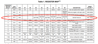
When debugging the PGA280, we sent the hex instruction 8300 to the PGA280 register 3 "set BUF time-out" (as shown in the figure). It should have got a return value of 19, but we did not receive any value, and the PGA280 did not respond.We suspect the chip didn't work because of the power supply.
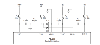
This is a typical power wiring diagram from the official documentation
This is a typical power wiring diagram from the official documentation
  • Hi Gang, 

    1) Yes, using VSP=+15V, VSN+-15V, VSOP=+5V, VSON=GND, DVDD=+3V and DGND=GND should be fine as shown on the power wiring diagram below.  Why have you mentioned that the issue may be related to the supplies?  Have you confirmed that the supplies are at the expected voltages above using a voltage meter?  Kindly provide a schematic showing the voltage supplies involved in your application along with the bypass capacitors.  Is the issue occurring on several devices or only one device? 

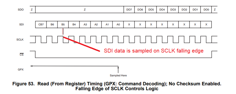
    2) Can you please provide an oscilloscope plot of the SPI interface including CS, SCLK SDI and SDO during the complete read transaction command:  1000 0011 0000 0000?  Please refer to Figure 52 of the datasheet.  Please place the oscilloscope probes right at the PGA280 SPI pins (CS, SCLK SDI and SDO). 

    The device samples the SDI data at the falling SCLK edge, so the SDI data should change/update during the SCLK rising edge and be stable during the SCLK falling edge.  Please let us know also the SCLK frequency used.  I assume the device is used in default configuration with the Checksum bit (CHKsumE) disabled (otherwise, please clarify if the CHKsumE has been enabled).

    Thank you and Kind Regards,

    Luis 

  • Hi Luis,

    1)The generation code of SPI comes from HAL library of STM32, the library version is V1.8.4, and STM32F103ZET6 is used by SCM.

    We connect the pins of SDI and SDO to form a closed loop. PA6(MOSI) <==> PA7(MISO)After writing 0x55 again, 0x55 can be read.

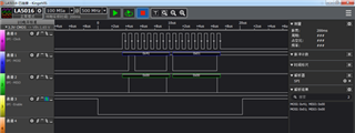
    2)This is the initialized waveform

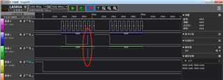
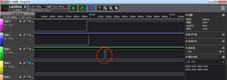
    This is the waveform of writing data, the data is 0x83, and no return value is received. However, there is a spike pulse in the picture, but I did not find the reason for the spike pulse. cs is high first, then pulled low, and finally pulled high. But the size of the picture is limited, there is no screenshot of the final CS high level.

    This is an enlarged view of the spike pulse

    Thanks,

    gang

  • Hi Gang,

    Thank you for the digital analyzer plots.

    - Can you provide a detailed schematic showing all the PGA280 bypass supply capacitors and voltages?

    - Have you tested only one device or various devices?  If you have tested only one device, can you try a fresh unit?

    - If the issue persists, can you provide an oscilloscope plot, placing the probes right at the CS, SDO,SDI, SCLK pins of the PGA280 (instead of a digital analyzer plot)?  The reason I ask for an oscilloscope plot, is that in some cases, excessive ringing or overshoot/undershoot could cause issues on the SPI communication and this issue may not show on the digital analyzer plot.

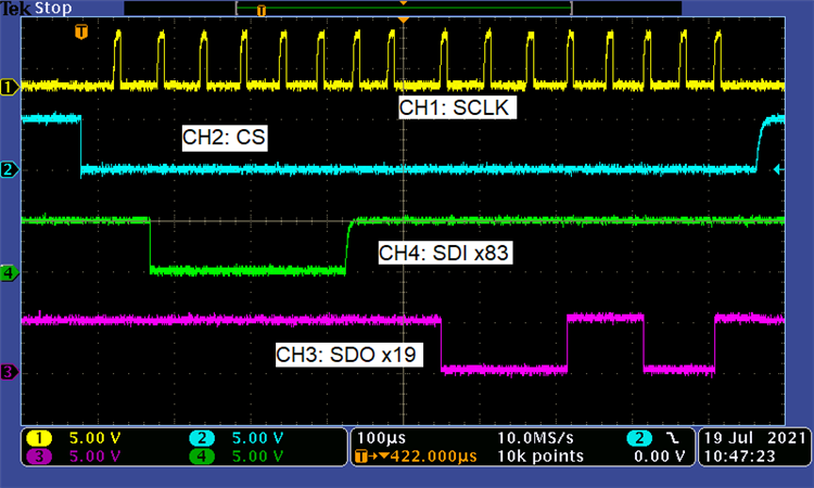
    After powering up the PGA280 device on the lab, and issuing the Read command x83XX, the device returns 0x19 as expected.  See oscilloscope shot below.  The oscilloscope probes were connected right at the PGA280 SPI pins.

    Thank you and Regards,

    Luis

  • Hi Luis,

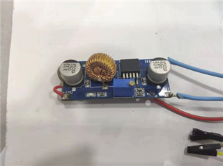
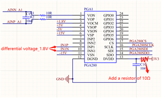
    This is our 3v3 power supply powered separately.

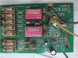
    This is our +15, -15, + 5V power supply.

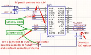
    AGND is connected to -15V via Schottky diodes, and digital GND is also connected to -15V via Schottky diodes.

    The existing PGA280 test board is built according to the typical circuit, but the power supply is a little messy. Now we only want to supply the digital power 3V3, as shown in the red circle in the figure. So whether the PGA280 chip can work.

    2)

    We have welded two boards and tested them respectively, but there is no output signal after sending input signal.

    3)

    The oscilloscope waveform is being tested. I will reply to you after the test.

    Thanks and Regards,

    gang

  • Hi Gang,

    It appears there are two separate challenges you are trying to resolve, one is the supply design, and a second issue is the microcontroller digital communication.  One suggestion is to debug the issues separately, one at a time.

    In order to debug the digital SPI communication, a suggestion is to clean-up / simplify the setup as much as possible. Start with a fresh PGA280 device using a linear bench supply performing a simple supply connection to the PGA280 board.  A triple bench supply with VSP=+15V, VSN=-15V, VSOP=DVDD==+3.3V may suffice to verify digital communication for now.  Ensure all the supplies are directly connected to the same ground potential through a low impedance connection (+15V/-15V, +5V and +3.3V should be referred to the same GND potential).  The microcontroller should be powered to the same +3.3V DVDD supply and also needs to be connected / referred to the same ground potential.

    Once you have confirmed with the oscilloscope the microcontroller READ/WRITE digital communication with a fresh PGA280 device, using a clean/simple bench supply set-up, then proceed with the power supply debug. 

    Please observe and ensure that the Absolute Maximum Ratings from Section 6.1 of the PGA280 datasheet (p.4) are not violated and ensure that all the supplies are referred to the same ground potential through direct, low impedance connections.

    Thank you and Regards,

    Luis

  • Hi Luis

    According to your tips, we adjusted the power supply, and we successfully read the correct value.

    Thank you for your constant help!!!

    Thank you very much,

    Gang

  • Hi Gang,

    That's good news!

    Thank you for letting us know,

    Kind Regards,

    Luis