This thread has been locked.

If you have a related question, please click the "Ask a related question" button in the top right corner. The newly created question will be automatically linked to this question.

OPA317-Q1: Voltage drop due to OPA317

Part Number: OPA317-Q1
Other Parts Discussed in Thread: OPA317, TINA-TI

Hello TI,

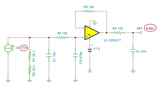
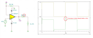
We are using a current source to test a current sense circuit. The given input DC current range is 1mA to 75mA.

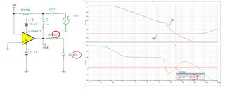
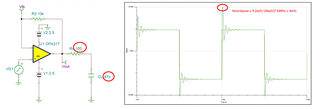
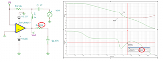
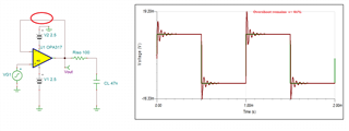
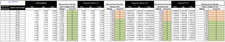
We are facing a voltage drop across R3 ranging from 3mV to 20mV as we increase the input current. Even if we depopulate D1 BAS40 diode.

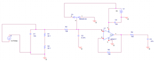
We would like to know if this is normal and why it is happening through the Opamp? Attaching the circuit below. 

regards,

  • Hi Rajat,

    R5 can destabilize the OPAmp by introducing a phase-lag in the feedback loop and by this eroding the phase margin. Replace R5 by a short circuit Relaxed

    Kai

  • Rajat,

    DC-wise your circuit should work as expected - see below.

    However, the issue you see is most likely caused by instability of the configuration - OPA317 may not be able to drive 47nF with 100ohm series output resistor.  Running AC simulation shows only 13 degrees phase margin while recommended minimum FM to assure stability over process and temperature variation is 45 degrees.

    A small-signal transient simulation confirms excessive overshoot of 46% - see below - while recommended minimum is 25%.

    Increasing a series output resistor, R4, to 220ohm increases the phase margin to 45 degrees (see below.).

    A small signal transient simulation confirms the stable operation with the overshoot of 25% - see below.

    Below I have attached Tina-TI simulation files for your convenience. 

    OPA317 Shunt AC Stability.TSC

    OPA317 Shunt TRAN Stability.TSC

  • Hi Kai and Marek,

    We are only working with DC source. 

    Performed the test practically and removed the Diode D1. 

    With increase in input current, the drop across the resistor increases. I would like to understand how opamp OPA317 is playing a role in the voltage drop?

    I simulated difference across the opamp inputs and the bias current is not more than 0.1uA.

    The the failures are at all temperature 85 deg cel and 25 deg cel. I tried feedback resistor removal but didn't help.

    Rajat J

  • Rajat,

    It doesn't matter that you work with DC source.  If the configuration is unstable (which I'm pretty sure it is),  it will oscillates on its own (no need for any input signal) resulting in the voltage drop across R3. 

    Thus, to answer your question how op amp plays a role in the voltage drop - it oscillates pulling current across R3. 

    Please place a scope at the output of OPA317 to verify that it oscillates - see below.

    To solve it, increase the R4 to 220ohm or remove 47nF C3 output cap.

  • Hi Rajat,

    it's a common mistake to believe that an OPAmp must not necessarily be stable at HF to be able to work properly at DC. According to Monsieur Fourier in every input signal step change -no matter how small- there's enough HF energy to stimulate the OPAmp to oscillate at the frequency where the phase margin is eroded.

    Even without any input signal the intrinsic noise of OPAmp is enough to start the oscillation.

    Yes, even an ideal, noisefree OPAamp without any input signal would start to oscillate, at the latest, when the supply voltage is being applied. There's no chance do this slowly enough...

    Kai