This thread has been locked.

If you have a related question, please click the "Ask a related question" button in the top right corner. The newly created question will be automatically linked to this question.

OPA544: Difference between simulations and the observations in the prototypes

Part Number: OPA544
Other Parts Discussed in Thread: OPA828, TINA-TI

Our design uses OPA544T.

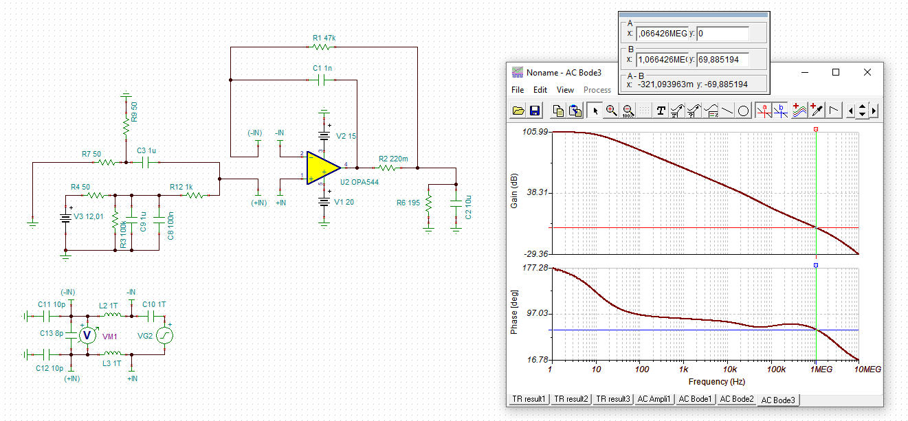
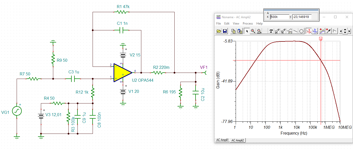
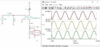
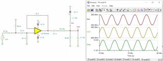
We have simulated the design using the model available. PFA .TSC file, FYR.

OPA544_12V_Switching_500KHz.TSC

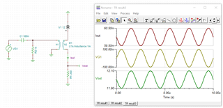
Waveforms from the prototypes Testing:
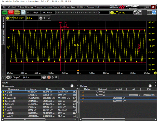
Vin:

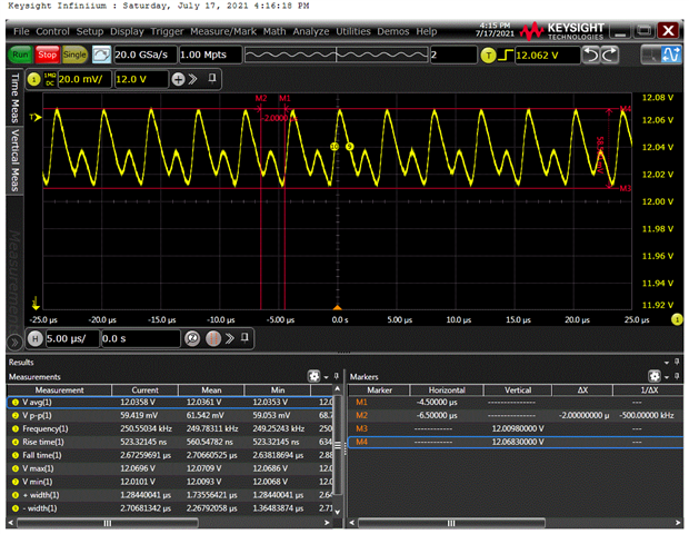
Vout with Oscilloscope set to DC mode:

Vout with Oscilloscope set in AC mode:
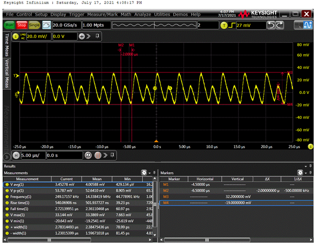
Observation:

We could see that the output waveform is distorted and not sine wave + DC offset. We are able to get the sinewave at the output upto 380KHz.

Pl let us know what is causing the output distortion and suggestions for improving the circuit.

  •  Hi ,

    You have 10uF at the output of the OPA544, and the current BW of the op amp configuration is remained at approx. 3.3kHz. Because of the 10uF capacitive load, the circuit is used up the most of available BW in OPA544 in compensating for the stability of the op amp.

    Have you removed 10uf capacitive load and shorted out the compensation circuit? My guess is that the circuit should work (short compensation resistor and open capacitor). 

    What is your output requirements in voltage amplitude , output current and capacitive load? I assumed that Vout frequency is 500kHz;  amplitude is +/-60mV riding on top of 12Vdc. What is the minimum capacitive load you need for the application?

    Best,

    Raymond

  • Hi Ponnusamy,

    at least, it looks stable in the phase stability analysis:

    ponnusamy_opa544_1.TSC

    Kai

  • But a bandwidth of 500kHz is not possible with this circuit:

    ponnusamy_opa544_2.TSC

    Kai

  • Hi Raymond,

    Thanks for the analysis & detailed response.

    Pl let me know how the current BW (approx. 3.3KHz) is calculated?

    We could see that our circuit works even for 350KHz also. How to relate the current BW and the max frequency which can be supported by the design?

    10uF Load is a requirement.

    >>What is your output requirements in voltage amplitude , output current and capacitive load?

    >>I assumed that Vout frequency is >>500kHz;  amplitude is +/-60mV riding on top of 12Vdc. What is the minimum capacitive load you need for the application?

    Vout: 12V DC +/- 50mV peak-peak (AC)

    Output Current: Switching Load - switches between 60mA (500uSec) & 10mA(10uSec)

    Output Current: Max 200mA (for a brief period)

    Capacitive Load: 10uF

    Vout / Vin Frequency Range: 5KHz to 500KHz

    Pl let us know the following:

    a. What is the root-cause of the issue we are observing?

    b. Will the circuit modifications help here?

    c. Any suggestion on the alternate implementation to achieve the required output?

    d. Any alternate devices will help?

    Best Regards,

    Pons

  • Hi Kai,

    Thanks for the analysis and the response. Slight smile

    What is the max bandwidth we can get with this circuit? We can allow some distortions in the output waveform (ex: waveform may be triangular instead of sinewave input).

    What limits the bandwidth of the circuit? What can be done to improve the bandwidth?

    Best Regards,

    Pons

  • Hi Ponnusamy,

    a. What is the root-cause of the issue we are observing?

    With Kai's simulation, the gain of the circuit is approx. -6dB up to 13-19kHz. At 300kHz, it attenuates at -18.7dB; at 500kHz, it attenuated at -23dB. As Kai pointed out, the circuit is unable to support the input signal. 

    In DC mode, it looks a bit strange also. I am unable to comment on it unless I see your 12Vdc supply reference vs. frequency. If the 12Vdc is from switching power supply, then I am not surprised. It looks like that 12Vdc may have up to 58mV ripple voltage on it (you did have 2.9kHz LPF filter after 12Vdc).

    In AC mode, the waveform looks the same as DC mode, my guess is that AC input signal may have coupled onto 12Vdc when DC mode measurement is made (speculation). 

    b. Will the circuit modifications help here?

    OPA544 is unable to meet the application, if 10uF capacitive load is required. What is the maximum current you need to source for the application? We need to have to use a high BW power amplifier to meet the requirements (depending on your output current requirements).

    What is your application?  If you just want to couple high frequency AC signal onto 12Vdc, you may adapt a different design approach (as alternative). .

    c. Any suggestion on the alternate implementation to achieve the required output?

    I will need additional design/application information from you. 

    d. Any alternate devices will help?

    The HS op amplifier team may have something that meets your requirements with the same op amp compensation approach. We are Precision Op Amp team, and our selections of high BW, high current power amplifiers are limited. (Our team is supporting op amp's BW < 50MHz, and HS op amp team is supporting op amp's BW > 50MHz). 

    If you can specify the maximum output current & voltage amplitude + 10uF capacitive load @500kHz,  we may be able to recommend possible options.  

    Best,

    Raymond

  • Hi Raymond,

    Thanks for the detailed response.

    Pl find our design requirements which would help you to suggest better devices and / or design options.

    Application: To design a power supply with known ripple (50mVp-p)

    >> If you can specify the maximum output current & voltage amplitude + 10uF capacitive load @500kHz,  we may be able to recommend possible options.

    Vout: 12V DC with (intentional) ripple of 50mV peak-peak (AC)

    Output Current: Switching Load - switches between 60mA (500uSec) & 10mA(10uSec)

    Output Load Current: Max 200mA (for a brief period)

    Capacitor at the output: 10uF

    Vout / Vin Frequency Range: 5KHz to 500KHz

    Pl note that we already have an LPF at the input of 12V reference with a cut of frequency of ~160Hz.

    Pl suggest possible design solutions to fix this issue based on the inputs provided.

    Best Regards,

    Pons

  • Hi Pons,

    Application: To design a power supply with known ripple (50mVp-p)

    I made a typo in the capacitive load while I am compensating the circuit. I will resubmit the circuit. 

    I need to think about the approach and get it back to you. 

    Best,

    Raymond 

  • Hi Raymond,

    Here is one of solution per your requirements will meet your 500kHz output signal + 10uF + up to 200mA load current. . 

    Looks like the proposed circuit with OPA828 contains 10nF instead of 10uF as the load / output cap. When simulated with 10uF cap the waveforms are not OK.

    I do not understand your intention of 12Vdc with ripple of 50mV ripple voltage. If the purpose is to coupling AC onto the 12Vdc bias voltage, I would think that you want to have low ripple and stable 12Vdc at the input.

    As you have mentioned, the purpose is to couple AC onto the 12V DC Output.

    I agree that we need to have a stable DC reference voltage at the input of the Op-Amp. Our current design uses output of an LDO (TPS7A4501DCQT) for this purpose.

    Once we have a working solution we can focus on to analyze and update the reference voltage. Hope this is OK.

    You may suggest alternate options including multiple Op-Amp solutions available to meet the functionality.

    If needed, pl transfer our query to other teams.

    Best Regards,

    Pons

  • Hi Pons,

    Your power application is running at 12Vdc and you'd like to inject a known frequency and amplitude in AC signal from 5kHz - 500kHz on top of 12Vdc.

    If you have a coupled inductor (gapped) that is running through 12Vdc + load, and coupled the AC frequency (5kHz - 500kHz) via the windings of the coupled inductor. The schematic looks like the following. 

    Without 10uf capacitive load + 200Ω:

    With 10uf capacitive load + 200Ω: AC ripple is "filtered" out at the load due to the pole (associated with 10uf capacitive load). 


    It is possible to increase the known ripple amplitude up to 500kHz at 12Vdc but your input AC voltage amplitude at the generator has to be increased significantly in order to overcome the -20dB/decade attenuation at the load. In addition, amplitude is a variable from 5kHz - 500kHz at a rate of -20dB/decade. 

    I0uf capacitor load's impedance decreased significantly as the frequency increases. At 500kHz, its impedance is approx. 1/(2*pi*500kHz*10uf) = 0.032Ω or 32mΩ. You will need to have large AC generator (or power amplifier) to drive the impedance at 500kHz (say, 60mVpk/32mΩ = 1.9Apk @500kHz).  

    AC Riding on DC 08032021.TSC

    I do not have an easy solution to your inquiry, but the above approach may work. You will need to select a coupled inductor to accomplish this, since 12Vdc will result a saturation of transformer instantly. The coupled inductor has to be unsaturated high current type, say it will not be saturated up to 10Adc @ 500kHz (likely ferrite based magnetic core). 

    After the above calculation, HS Op Amp team does not have an power amplifier to meet your need either ( I can ask the HS Op Amp Team). 

    If you have additional questions, please let me know. 

    Best,

    Raymond

  • Hi Pons,

    Would you be able to tell me why you will need 10uF capacitive load at the output of the application?

    If a designer is using power amplifier as a voltage regulator, I understand why it may be necessary to use large capacitive load at its output. However, such application requires only low BW in design, since the larger capacitive load at the output of an amplifier reduced the BW the op amp's BW significantly. The large capacitive load introduces a second low frequency pole in the op amp's closed loop, which it has to be compensated in order to achieve the loop stability.

    My yesterday's reply is a technique used in Power Line Communication (PLC), where AC signal is coupled onto a power line (DC or AC power) in communicating within a power distributed network. Your design requirements resemble a particular PLC application with one exception, which the 10uf capacitive load is typically allocated at 12Vdc regulator's output or power source side or at high side. 

    https://www.ti.com/lit/ds/symlink/afe032.pdf?ts=1628092955704&ref_url=https%253A%252F%252Fwww.ti.com%252Fproduct%252FAFE032

    https://www.ti.com/lit/ug/sbou223/sbou223.pdf?ts=1628092976839&ref_url=https%253A%252F%252Fwww.google.com%252F

    So I'd like to know why 10uF capacitive load has to be in parallel with resistive load. As I indicated, if a generated pole from 10uf capacitive load is within 500kHz AC signal, you are unable to couple the entire 5kHz-500kHz AC frequency onto the 12Vdc line. It may work at lower AC frequency, but it will start to attenuate the input signal near and above the cutoff frequency of the pole. Another way to look at this: the  Rth*C_load time constant generated from the Thevenin Resistance ((powerline_overall_impedance)||60Ω) and 10uF_Capacitive_load << 1/500kHz in order to pass the AC signal up to 500kHz. Otherwise, the input signal will be "filtered" out by the pole in (1/(1+sC_load*Rth).  

    I am starting to understand the difficulties of the application requirements. Even with the use of High Speed Power Amplifiers, the options are very limited unless we understand why driving 10uf capacitive load is necessary.   

    If you need further assistant, please let me know. 

    Best,

    Raymond 

  • Hi Pons,

    Here is another solution with capacitive coupling. It may need some fine tuning (deque the circuit), but it may meet your application. Please let me know. 

    ponnusamy_opa544 08042021.TSC

    Best.

    Raymond

  • Hi Ponnusamy,

    keep in mind that a 10µF cap presents an impedance at 500kHz of

    1 / 2 / pi / 500k / 10µ = 32mOhm !

    This looks like short circuit. So it really makes no sense to request from your circuit a bandwidth of 500kHz into a capacitive load of 10µF.

    You can build a circuit offering a bandwidth of 500kHz in combination with a standard capacitive load of let's say 100pF or 1nF and then state that this circuit is stable with a capacitive load of up to 10µF. This would make sense. But it does not make sense to postulate a bandwidth of 500kHz into a capacitive load of 10µF.

    Also keep in mind, that the TINA-TI's AC analysis calculates the frequency response by the help of an excitation signal having a vanishing small amplitude. Because of this the AC analysis might give a good looking result while the measurement at the real circuit shows issues.

    Also, the SPICE model is built for normal and standard operation and not for operation with a 32mR short circuit at the output. So you should not expect proper results from the simualtion when short-circuiting the output of OPAmp. The observed distortion could be the result of catastrophic decrease of open-loop gain due to the short circuit condition at the output, for instance.

    Kai

  • Hi Ponnusamy,

    I am going to close this inquiry for now. If you have additional questions, you may still open the thread or create a new one via E2E. 

    Best,

    Raymond